


Patents Completed.
Page 20
If you've noticed an error in this article please click here to report it so we can fix it.
Complete specifications of the following patents will be sent to any address in the United Kingdom by the Sale &ranch, Patent Office, Holborn, W.C., upon receipt of eightpence per copy.
A Motor-driven Tip Wagon.
Clayton and Co., No. 26,570, dated 8th November, 1911.—This is a mechanism for performing the tipping operation by means of power from the motor. The raising gear is made up with two screws, one working within the other and driven by means of a chain off the countershaft. The main driving sprocket connects with the countershaft by a sliding dog-clutch made in one piece with it, and as soon as it is disengaged, the chain gear for the tipping screw is at once put into operation by other dog-clutch connections. The countershaft is turned by the engine through the usual variable gear, forwardly for raising the tip mechanism, and the reverse way for lowering.
Concentric Tappet Valves, T. A. E. Nicholson, No. 25,761, dated 18th November, 1911.—The object of this invention is to arrange the valves in a detachable sleeve or easing, so that they can be removed without taking off the cylinder or the cylinder head, or disconnecting either the inlet or exhaust pipes. It is also convenient for the purpose of carrying a complete spare set of valves ready mounted, and only requiring to be placed in position. A sleeve or valve casing is secured in the cylinder head by bolts, and this provides a valve seating for the hollow tappet valve. Within the hollow valve there is an ordinary mushroom-headed valve of which the stem works in aguide on the hollow valve.
The inlet and exhaust pipes are taken off laterally from the two valves, suitable ports being cut in the side of the hollow valve to allow this.
A Centrifugal Speed Indicator.
If. Duncan and B. Elion, No. 2225, dated 27th January, 1912.—In this speed indicator a flattened spherical chamber is partially filled with steel balls. A disc is provided inside the chamber, and this is coupled to a spring control, and also to a pointer moving over a scale. The spherical chamber is rotated from a road wheel, and the centrifugal action on the balls causes them to collect round the largest circumference of the sphere ;
in so doing they grip the disc with a force that is proportional to the speed at which they are revolving, and so give a reading also proportionate to the speed. This device was first illustrated in the " O.M." in February last.
Switch Locking Gear.
C. A. Vandervell and A. H. Midgley, No. 4682, dated 24th February, 1912.— It is desirable to provide some means of locking electric switches on a motorvan to prevent anyone tampering with them. Provision must be made for locking 'switches, therefore, either in their " on " or " off " positions. According to the present invention—here illustrated as applied to tumbler switches—a bar is provided which is hinged to swing into position intermediate to the " on" and " off " positions of all the switches, The head of the tumbler is thus on the one side or the other of the bar in its locking position, and it cannot be moved until the bar has been removed. Any convenient method of locking the bar in this position may be used.
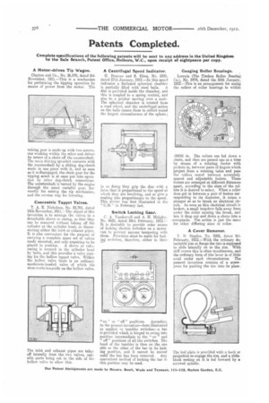
Gauging Roller Bearings.
Lorrain (The Timken Roller Bearing Co.), No. 2474, dated the 30th January, 1912.—This is an arrangement for sizing the rollers of roller bearings to within
.00025 in. The rollers are fed down a chute, and then are passed one at a time by means of a rotating feeder with pockets in, between pairs of fingers which project from a rotating table and pass the rollers round between accurately spaced and adjustable feelers. These feelers are arranged at different distances apart, according to the sizes of the rollers it is desired to select. When a roller does get in between a pair of feelers corresponding to its diameter, it raises a plunger so as to break an electrical circuit. As soon as this electrical circuit is broken, a. small trapdoor falls away from under the roller causing the break, and lets it drop out and down a chute into a -receptacle. The action is just the same for other differing sizes of roller.
A Cover Remover.
T. D. Staples, No. 3285, dated 9th February, 1912.—With the ordinary detachable rim or flange the tire is supposed to slide laterally on to the rim. With stiff covers this is often troublesome, and the ordinary form of tire lever is of little Etvail under such circumstances. The present invention consists of a screwpress for pushing the tire into its place.
The bed plate is provided with a hook or projection to engage the rim, and a slideblock resting on it is fed forward by a screwed spindle.