


Development in Rubber Suspension Systems
Page 52
If you've noticed an error in this article please click here to report it so we can fix it.
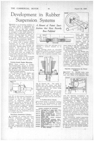
THERE is an increasing tendency to employ rubber in suspension systems, not only as an adjunct to leaf springs, but as the sole resilient member. In modern designs the rubber is arranged to take shear stresses, as distinct from compression stress, and a German example forms the subject of patent No. 488,888, from Cietefo G.esellschaft fiir Technischen Fortschritt m.b.H„ 13, Woyrschstrasse, Berlin.
The scheme illustrated is as applied to a chassis with a central, tubular backbone (I) to which are attached cros-members (l1) for carrying the bodywork. Rubber blocks (1) are canized to the ends of the crossmembers, and besides to the wheelassembly back plate. The axles (2), at their inner ends, are swaged to a semi-circular form and pivot about the outside of the tubular frame.
That such a scheme as this is feasible is a great tribute to the modern methods of uniting rubber to 'metal.
Tubular-chassis Engine Mounting.
THE Tatra concern, of Prague, Czechoslovakia, always to the fore with novel designs, discloses in patent No. 488,789 a new method of mounting the power unit on a chassis having a central tubular member.
The drawing shows the engine and the front of the chassis (3). The engine, complete with radiator and gearbox, is carried upon an arm (4) extending from the chassis. A second arm (2), in this instance detachable, is attached to the top and matters are arranged so that a line joining the points of suspension would pass through the centre of gravity of the engine. Rubber blocks (1 and 5) are interposed between engine and hangers to form resilient mountings. Another scheme shown in the same patent employs the lower arm as a means for attachment for the suspension system of swinging half-axles.
Steel-lined Aluminium Cylinders.
ASCHEME for casting steel liners into aluminium cylinders, thus forming a: homogeneous whole, is described in patent No. 489,084, by Fichte] and Sachs A.G., of Schweinfurt, Germany. This patentee states that the high temperature of molten steel renders the 'operation of pouring into
A34 aliiminium a risky one, and goes on to describe a method claimed to be suCcessful.
The drawing shows an air-cooled aluminium' cylinder in process of being lined ; it will be noted that a substa atial core (1) is inserted centrally, lead ing to runners (2). The metal is poured into the centre and flows upward into the annular space between core and cylinder, the whole being simultaneously rotated.
The presence of the cold core is said to absorb sufficient heat to prevent melting of the cylinder, although the metal is sufficiently hot to form a homogeneous mass with the outer alloy casing.
A Cushion-driven Clutch.
CLUTCH design is gradually tending towards the ine oiporation of some form of cushion drive, as it has been found that much transmission wear is due to torsional vibration and uneven torque impulses, both of which originate in the engine. The latest design in this direction is shown in patent No. 486,917, coming from M. Goldschmidt, 15, Leerbachstrasse, Frankfort-on-Main, Germany.
The drawing shows the flexible connection in assembly with a standard type of clutch. A flanged ring (1) is attached to the friction plate, whilst a second ring (2) is riveted to the central, splined boss. The two rings are cut away at opposed points around the periphery, and the intervening space is filled with rubber which, by vulcanization, converts the two flanges into a one-piece structure.
Injection Arrangements for Petrol Engines.
DATENT No. 488,238 deals with petrol engines employing fuel injection, and whilst it is concerned only
with the injection arrangement the drawing is interesting in so far as it discloses the general combustion arrangements of an engine of this type. The patentee is Pallas Apparate G.m.b.H., 71-76, Ackerstrasse, Berlin.
The most vital problem in the injection system appears to be the cooling of the nozzle, and to this end the injector is made to touch the engine at only one point, the conical seating (2). Holding-down pressure is applied by a setscrew (4) mounted in a stirrup bar (5), and cooling is assisted by forming fins on the body.
The combustion system apparently employs a precombustion chamber (1) with a constricted neck (3) into which the inject& discharges. Overhead valves are used and the cylinder is liberally provided with cooling passages. It will be noted that electric ignition is employed: