


A KINETIC ENGINE STARTER.
Page 21
Page 22
If you've noticed an error in this article please click here to report it so we can fix it.
Details of an Interesting Device Utilizing the Flywheel.
THE STARTING of heavy lorry engines is a trouble which has not yet been satisfactorily solved. As a result of many years' research, three aystems-are in general use—direct hand cranking, electric starters, and mechanical starters. Of these, direct hand cranking is very unsatisfactory, particularly in eases where the driver is a woman. Mechanical starters do no usually increase the power available for starting, but merely enable it to be applied from the driver's seat ; incidentally a certain amount of this power is usually lost in transmissiou to the crankshaft. .
Electric starters have given a certain amount of satisfaction and are very convenient to use when the engine is warm, but they take a considerable amount of current when used for starting in engine from cold. If an engine does not start and several attempts are made with an electric starter, there is a great danger of ruining the accumulators.
An analysis of the resistances against which an engine has to be turned show them to be of three sorts : (1) the first stroke piston Pressures—compression in one cylinder and vacuum in another • (subsequent stroke pressures are balanced to -a certain degree by the release of work done); (2) the friction of pistons, bearings, valves, etc. ; (3) the inertia of all parts that have to be set in motion.
To summarize these resistancesa-during the first half revolution it is necessary to apply the whole of the piston pressure work, half the frictional work of a revolution, and the whole of the kinetic energy required for the speed reached, which, in hand turning with a medium-sized engine, may be taken at about 90 ap.m. , It has been calculated that the work done during • this first half revolution averages about.3 h.p. even with a small engine. In comparison with this figure it may be noted that the sustained working power of a man turning a handle is calculated to be only about 1-13th h.p. ; so that, with even a small engine, four times. a man's normal output of work is required in starting up, and this •figure in larger engines has to be considerably exceeded. The inference to be drawn from this is that, although the total amount of work involved in starting is very small, the rate at which it must be applied is very high. .
What is required, therefore, is not so much a large secondary power unit as an accumulator to store up the small human energy for a few seconds and then let it loose upon the engine with a rush ; in other words, a mechanical -accumulator . of energy would solve the problem as well as, if -not better than, a secondary power system installed for this purpose..
An invention known as the Kinetic Starter and patented by A. H. Clark, Sunningdale, Molesey, Surrey, has recently been brought to our notice. It is a very simple Ake which utilizes the engine flywheel as an accumulator of energy, and although hand power can be applied to it as slowly or as rapidly as the driver wishes, the power is subsequently applied to the engine at three or four -times the maximum rate possible by direct hand .cranking.• • Other forms of ateChanical accumulators, including springs and a geared flywheel, are covered in the patent, but the use of the engine flywheel, where this can be arranged, is the simplest and most efficient, as it adds practically no weight to the-trehicle, and rer duces by 80 per cent, that portion of the power used
in overcoming inertia when the engine is started, as in most engines the flywheel itself represents this amount of the total inertia..
In order to use the flywheel as air accumulator of energy, it would be rather difficult to embody thedevice in existing vehicles, but it would be a fairly simple matter to alter slightly the arrangement of the flywheels of engines under construction.
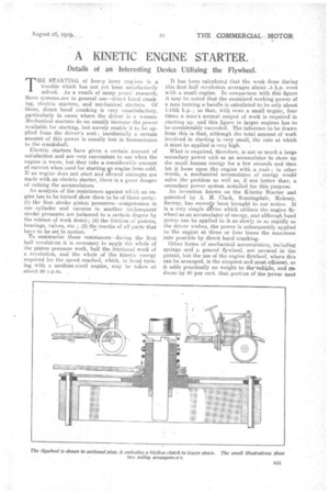
For the purposes of the invention, the flywheel must be capable of rotating freely on the crankshaft, and the illustration which we reproduce shows clearly how this is effected. On the flywheel centre is turned a square thread on which is mounted a small pulley wheel, which, when fully screwed up, engages the flywheel by means of small dog clutches.
The pulley is rotated through the medium of a round leather belt, by a large pulley wheel situated on a bracket bolted to the dash and operated by a handle.
The pulley, when rotated, turns the flywheel at whatever speed is desired, and when this speed is reached and the turning force is no longer applied the pulley unscrews itself from the square thread on the flywheel boss; in doing so it compresses a spiral spring, this causes a sliding ring at the front end 'of the spiral spring to 1130ve in the same direction and to engage its dog teeth with those on the crankshaft. These teeth are made in two-step form, in order to
overcome the difficulty of engaging a aog clutch while one portion is in rapid motion and the other stationary. The sliding ring is connected. to the flywheel by long dogs, and by these it locks the flywheel to the crankshaft.
In order to prevent the great. shock which would occur if the rapidly-'revolving flywheel were solidly locked to the crankshaft, africtional, flanged coupling connects the flywheel centre with its rim, and this frictional coupling can be adjusted to give the necessary slip on engagement, which is normally about 2 ins, round the circumference of the centre.
The adjustment of the friction device is obtained by the use of thick or thin washers as the case may be, between the friction plate and the run of the flywheel, which naturally. have the effect of decreasing or increasing the pressure on the flywheel centre.
On lighter vehicles, such as delivery vans, the starting pulley wheel may be attached to the steering. columns, While the engine is running the pulley rests on the parallel portion of the flywheel centre situated between the square thread and the sliding ring. To assist in the disengagement of the sliding ring dogs when the vehicle has to be started, a spiral spring is situated between a collar on the crankshaft and a collar on the former.