


The Timing of Petrol Engines.
Page 14
Page 15
If you've noticed an error in this article please click here to report it so we can fix it.
By T. 0. Pugh.
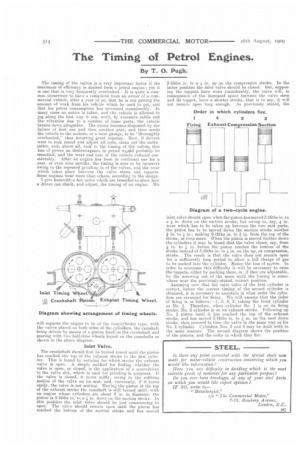
The timing of the valves is a very important factor if the maximum of efficiency is desired from a petrol engine; yet it is one that is very frequently overlooked. It is quite a common occurrence to have a complaint from an owner of a commercial vehicle, after a year or so, that he is not getting the amount of work from his vehicle which he used to get, and that his petrol consumption has increased considerably. In many cases no notice is taken, and the vehicle is allowed to jog along the best way it can, until, by excessive rattle and the vibration due to a number of loose parts, the vehicle breaks down altogether. The owner becomes disgusted by the failure of first one and then another part, and then sends the vehicle to the makers, or a local garage, to be "thoroughly overhauled," thus incurring great expense. Now, if drivers were to look round and adjust all nuts, clean out the carburetter, and, above all, look to the timing of the valves, this loss of power an dextra,vagance in petrol would probably be remedied, and the wear and tear of the vehicle reduced considerably. After an engine has been in continual use for a year, or even nine months, the timing is sure to be incorrect owing to the repeated grinding in of the valves, and the wear which takes place between the valve stems and tappets. Some engines wear more than others, according to the design. I give herewith a few notes which are intended to show how a driver can check, and adjust, the timing of an engine. We will suppose the engine to he of the four-cylinder type, with the valves placed on both sides of the cylinders, the camshaft being driven by means of a pinion fixed on the crankshaft and gearing with two half-time wheels keyed on the camshafts as shown in the above diagram.
Inlet Valve.
The crankshaft should first be turned round until the piston has reached the top of the exhaust stroke in the first cylinder.. This is found by noticing for which stroke the exhaust valve is open. A simple method for finding whether the valve is open, or closed, is the application of a screwdriver to the valve slot, which is used for grinding-in purposes. If the valve is closed, it turns stiffly, owing to the rubbing motion of the valve on its seat, and, conversely, if it turns easily, the valve is not seating. Having the piston at the to of the exhaust stroke the camshaft is still turned until, with an engine whose cylinders are about 4 in, in diameter, the piston is 3-16ths in. to a in, down on the suction stroke. In this position the inlet valve should be just commencing to open. The valve should remain open until the piston has reached the bottom of the suction stroke and has moved
3-16ths in. to a in. up on the compression stroke. In the latter position the inlet valve should be closed. But, supposing the tappets have worn considerably, the valve will, in consequence of the increased space between the valve stern and its tappet, have a shorter stroke, that is to say, it will not remain open long enough. As previously stated, the
inlet valve should open when the piston has moved 3-16th8 in. to a in. down on the suction stroke, but owing to, say, in. wear which has to he taken up between the two said parts, the piston has to be moved down the suction stroke another
in. to in., making 9-I6ths in. to in. from the top of the stroke, or even more. When the piston is moved further down the cylinders it may be found that the valve closes, say, from
in. to in. before the piston reaches the bottom of the stroke instead of 3-16ths in. to in. on the up, or compression, stroke. The result is that the valve does not remain open for a sufficiently long period to allow a fall charge of gas to be sucked into the cylinder. Hence the loss of power. In order to overcome this difficulty it will be necessary to raise the tappets, either by packing them, or, if they are adjustable, by the screwing out of the same until the timing is somewhere near the previously-stated, correct position.
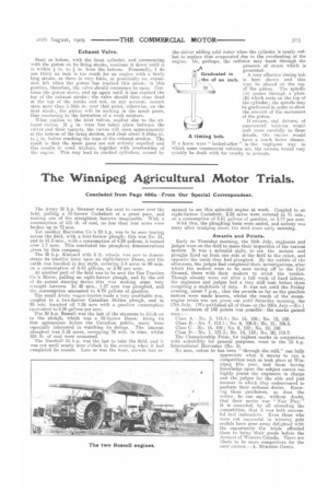
Assuming now that the inlet valve of the first cylinder is correct, before the correct timing of the second cylinder is obtained, it is necessary to ascertain in what order the cylinders are arranged for firing. We will assume that the order of firing is as follows ;--1, 3, 4, 2, taking the front cylinder as No. 1. Therefore, when cylinder No. 1 is on its firing stroke, No. 2 cylinder is on its exhaust stroke. Following up No. 2 piston until it has reached the top of the exhaust stroke, and has moved 3-1fiths in. to in. on the next down stroke, then proceed to time the valve in the same way as for No. 1 cylinder. Cylinders Nos. 3 and 4 may be dealt with in the same manner. The second diagram shows the position of the pistons, and the order in which they fire.
Exhaust Valve.
Start as before, with the front cylinder, and commencing with the piston on its firing stroke, continue it down until it is within in. to ,1 in. from the bottom. Personally, I do not think an inch is too much for an engine with a fairly long stroke, as there is very little, or practically no, expansion left when the piston has reached this point; in this position, therefore the valve should commence to open. Continue the piston down, and up again until it has reached the top of the exhaust stroke; the valve should then close dead at the top of the stroke and not, on any account, remain open more than 1-16th in. over that point, otherwise, on the next stroke, the piston will be sucking in the spent gases, thus conducing to the formation of a weak mixture.
What applies to the inlet valves, applies also to the ex haust valves. If in. wear has taken place between the valves and their tappets, the valves will open approximately at the bottom of the firing strokes, and close about 9-16ths in. to !, in. before reaching the tops of the exhaust strokes. The result is that the spent gases are not entirely expelled and this results in weak mixture, together with overheating of the engine. This may lead to cracked cylinders, calmed by
the driver adding cold water when the cylinder is nearly redhot to replace that evaporated clue to the overheating of the engine. Or, perhaps, the radiator may burst through the pressure of steam which is generated.
A A very effective timing bob is here shown and this may be placed on the top of the piston. The spindle (A) passes through a plate (B) which rests on the top of the cylinder ; the spindle may be graduated in order to show the amount of the movement of the piston.
If owners, and drivers, of commercial vehicles would look more carefully to these A timing bob. details, the engine would have a much fairer chance. If a horse were " looked-after " in the negligent way in which some commercial vehicles are, the owners would very quickly be dealt with for cruelty to animals.