


Injection Pump With Pressure Lubrication
Page 36
If you've noticed an error in this article please click here to report it so we can fix it.
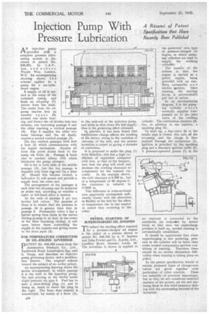
AN injection pump provided with a complete pressure lubricating system is diss closed in patent No. 546,651, by C.A.V., Ltd., and others, Warple Way, London, W.3. An accompanying drawing shows t ii e scheme applied to a pump for a six-cylindered engine.
A supply of oil is carried in the sump of the camshaft casing, and feeds an oil-pump (7) driven from the shaft. The outlet from the oilpump renches first an annular space (6) around one main bear ing, and thence the oil'divides into two streams, one traversing passage 5 and the other reaching a vertical passage
(8). Pipe 5 supplies the othertwo main bearings and the oil finally reaches a second vertical passage (3).
The two vertical passages both feed a bore (2) which communicates with the tappet mechanism. Surplus oil from this point drains back to the sump via holes (4). Passage 8 leads also to another oilway (16) which lubricates the pump plungers.
Oil is fed to both ends of the middle passage (2), but the top passage is supplied only from ono end via a filter (9). Should this become choked, a ball-valve (1) will unseat and provide a supply from the other end.
The arrangement of the passages is such that the oil-pump can be mounted at either end, according to whether a rightor left-hand drive is desired.
At the ends of passage 2 are two further ball valves. The purpose of these is to ensure that the pressure in passage 10 is greater than that in passage 2. Presumably valve 1 has a lighter spring than those in the valves feeding passage 2. so that, in the event of the filter becoming choked, it will open before those controlling the supply to the tappets and giving access to the drain pipes (4).
FOR TEMPERATURE CORRECTION IN OIL-ENGINE GOVERNOR
PATENT No. 546,358 comes from the
1 Automotive Products Co., Ltd., Tachbrook Road, Leamington Spa, and G. Trapp, and describes an injectorpump governing device, and a modification thereto. The original scheme formed the subject of an earlier patent.
An accompanying drawing shows the earlier arrangement, in which passage
2 is the inlet to the injection pump, the fnel arriving at the device under slight pressure via pipe 3. Fuel has to pass a close-fitting plug. (1) and in doing so, tends to move the plug to the right. The force thus created is transmitted, by means of a lever (4),
to the rack-rod of the injection 'pump, and tends to shut down the fuel supply; thus is the governing effect obtained.
In practice, it has been found that temperature change affects the working of the device, owing to the variation of viscosity of the fuel, and the present invention is aimed at giving a meastfre of correction. '
It is proposed to make the plug frOm Bakelite; this has a. high coefficient of expansion compared with iron, so that as the temperature rises the plug will swell and decrease the working clearance to compensate for the reduced viscosity. In the example shown, the cold clearance is 0.005 in., but at a temperature of 60 degrees C. the clearance is reduced to 0.0033 in.
This difference in cross-sectional area apparently corresponds sufficiently closely with the alteration, in fluidity of the fuel for the effect of temperature rise in one respect to cancel that occurring in the other.
PETROL STARTING OF SUPERCHARGED OIL ENGINES er0 reduce the starting effort required 1 for a pressure-charged oil engine is the object of a scheme shown in patent No. 546,722 by A. F. Sanders and John Fowler and Co. (Leeds), Ltd., Leathley Road, Hunslet, Leeds, 10. The invention is shown as applied to the patentees' own type of pressure-charged oil engine, in which pumping cylinders are used to supply the working
The essence of the scheme is that the engine is started as a petrol engine, being provided with an auxiliary carburetter a n d
electric ignition. Once running, the starting Set-up is automatically put out of action.
In an accompanying diagram, 5 is the pumping cylinder .w hich normally supplies compressed air to the. inlet valve of the Working cylinder. The combustion chamber (4) has, in addition to the injector, a sparking plug (3).
To start up, a disc-valve (6) in the intake pipe is closed, this cuts off the air-pump, and the charge is then inspired through the carburetter (1). Ignition is provided by the sparking plug and a standard ignition outfit (2). A pressure-operated piston (7) in the air reservoir is connected to the auxiliaries (as indicalled by dotted lines) so that once the supercharge pressure is built up, normal running is automatically established.
It: should be appreciated that when supercharging is not occurring, pressure in the cylinder will be lower than under normal compression-ignition conditions of running. Therefore there should be no serious detonation difficulties when Awning is taking place on patrol.
In the patent specification details of certain proposed types of change-over valves are given together with particulars of other controls. These are naturally of practical importance, but as they do not constitute essential features of the patent, we are not outlining them in this brief summary dealing with the outstanding features of the invention.