


A Road and Rail Ammunition Train A New Universal for Front-wheel Drive
Page 32
Page 33
If you've noticed an error in this article please click here to report it so we can fix it.
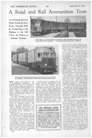
An Interesting American Outfit, Named the AutoRailer, Expressly Built for Transporting, on the Highway or the Rail Track, the Products of Ordnance Factories.
unique train shown in the accompanying illustrations was designed and built for the transportation of bombs, shells and explosives at one of the great ordnance plants in the United States. It is named the AutoRailer, because it operates equally well on highways and rails, and the design and construction follow automobile practice. '
The train is claimed to be the first of its kind, but locomotives, buses, lorries and trailers mounted on the same kind of dual-purpose under-trucks have for the past seven years, been in daily service on American railways. The builder, the Evans Products Co., of Detroit, Michigan, had. already supplied, for national defence service, such Auto-Railer units as explosives trucks, fire-fighting trucks, ambulance, and inspection cars., Adaptation of the undercarriages of such vehicles, so that they can run with the same facility on railway rails and the highways, passing readily from one to the other without stopping, provides a flexibility that solves a number of transportation problems, particularly the rehandling of loads for short hauls. While the train shown was designed for the movement of munitions, it is obviously well suited for tranaporting materials of Many other kinds.
A30
Driving power and braking force are applied through high-pressure pneumatic tyres. which support all the weight of the train and load when on the highway and 80 per cent. whets on rails and have special squeegee-type treads. Superior traction afforded by the rubber tyres and their ready absorption of shocks make possible the use of lightweight materials in construction. This results in lower initial cost as compared with conventional locomotive and goods-van construction, apart from important operating economies, The maker, therefore, regards such trains as
ideal for use by large industrial companies and by railways for branch-line 'operation and for switching vans in railway yards. •
The " locomotive" is powered by a 125 h,p. petrol engiue, has a rated payload capacity of 6 short tons, and hauls two goods vans each of 15 tons capacity, but the toxin has a gross load capacity of 90,000 lb. It runs on 42 36 by 6-in. tyres, of which 90 are dual mounted.
The four-wheeled undercarriage trucks are swivelled to the " locomotive " and van frames and mechanically interconnected so that when running on the highway all wheels follow approximately in the tracks of the prime mover's front wheels, which are steered as in a lorry. The van wheels are steered by drawbars connecting them to the "locomotive " and to each other.
For, operation on rails, each set, of wheels is provided with a pair of flanged steel pilot wheels to guide and hold them on the rails. These pilot wheels are lowered and raised vertically by pneumatic pressure in compressed-air cylinders controlled from the " locomotive " cab by electro-pnenmatic valtes.
To guide the train from the highway on to the rails without stopping, the pairs of pilot wheels are lowered successively as each set of pneumatic tyres mounts the rails, and when leaving the rails they are raised in the same order. The train is equipped with-standard railway air brakes controlled from the " locomotive " cab.
The vans and the load compartment of the " locomotive " have sliding side doors that open to a width of 5 ft. Sins. and with swinging end doors which open the full width of the body,. Overall length of the " locomotive " is approximately 22 ft. 6 ins., and of the., van 28 ft. Maximum width of each is 8 ft. and inside width and height are respectively 7 ft. 7 ins. and 6 ft. 8 ins.
The idea of building a vehicle for use both on the 'road and the rail is, of course, not new, and readers will doubtless recollect that the type was tried out experimentally in this country and on the Continent befbre the war. Maybe it has virtues to support its employment in strictly defined spheres, but its possibilities for wide commercial application can be disregarded.
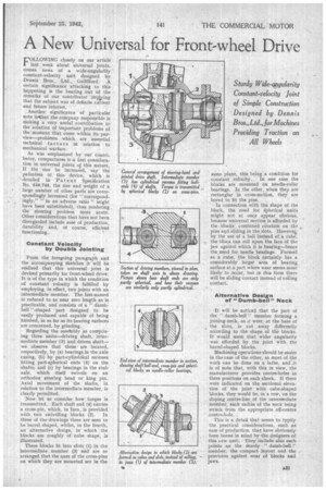
FOLLOWING closely on our article last week about universal joints, comes news of a wide-angularity constant-velocity unit designed by Dennis Bros„ Ltd., Guildford. A certain significance attaching to this happening is the bearing out of the remarks of our contributor implying that the subject was of definite current and future interest.
Another significance of particular note is+that the company responsible is making a very useful contribution to the solution of important problems of the moment that come within its purview—problems which are essential technical factors in relation to mechanical warfare.
As was emphasized by our contributor, compactness is a first consideration in universal joints of this nature. If the size be increased, say the patentees of this device, which is detailed in Patent Specification No. 546,745, the size and weight of a large number of other parts are correspondingly increased (for " correspondingly," " in an adverse ratio " might have been substituted), thus rendering the steering problem more acute. Other considerations that have not been disregarded include ease of production, durability and, of course, efficient functioning.
Constant Velocity by Double Jointing From the foregoing paragraph and the accompanying sketches it will be realized that this universal joint is devised primarily for front-wheel drive. It is of the type in which the condition of constant velocity is fulfilled by employing, in effect, two joints with an intermediate member. The last-named is reduced to as near zero length as is practicable, and consists of a " dumbbell "-shaped part designed to be easily produced and capable of being finished, in so far as its bearing surfaces are concerned, by grinding.
Regarding the assetably as comprising three units—driving shaft, intermediate member (3) and driven shaf t— we observe that these are located, respectively, by (a) bearings in the axle casing, (b) by part-cylindrical recesses fitting part-spherical ends (4) on the shafts; and (c) by bearings in the stub axle, which itself swivels on an orthodox steering head or king pin. Axial movement of the shafts, in relation to the intermediate member, is clearly permitted.
Now let us consider how torque is transmitted. Each shaft end (4) carries a cross-pin, which, in turn, is provided with two swivelling blocks (2). In three of the drawings these are seen to be barrel shaped, whilst, in the fourth, an alternative design, in which the blocks are roughly of cube shape, is illustrated.
These blocks fit into slots (I) in the intermediate member (3) and are so arranged that the axes of the cross-pins on which they are mounted are in the same plane, this being a condition for constant velocity. In one case the blocks are mounted on needle-roller bearings. In the other, when they are rectanglar in cross-section, they are bored to fit the pins.
In connection with the shape of the block, the need for spherical units might not at once appear obvious. because universal motion is afforded by the blocks combined rotation on the pins and sliding in the slots. Iloweve‘, by the use of a ball instead of a cube, the block can roll upon the face of the jaw against which it is bearing—hence the need for needle bearings. Formed as a cube, the block certainly has a considerably larger area of bearing surface at a part where wear seems most likely to occur, but in this form there will be sliding contact instead of rolling contact.
Alternative Design of "Dumb-bell" Neck It will be noticed that the part of the " dumb-bell" member forming a joining-neck, as it were, at the base of the slots, is cut away differently according to the shape of the blocks. It would seem that wider angularity was afforded by the joint with the barrel-shaped blocks.
Machining operations should be easier in the case of the other, as most of the work can be done on a lathe, and it is of note that, with this in view, the manufacturer provides centre-holes in three positions on each cheek. If these were indicated on the sectional elevation of the joint with cube-shaped blocks, they would be, in a row, on the sloping centre-line of the intermediate member, each radius of the neck being struck from the appropriate off-centre centre-hole. .
This is a detail that seems to typify the practical considerations, such as ease of production, that have obviously been borne in mind by the designers of this new unit. They include also such points as the sturdy " dumb-bell " member, the compact layout and the provision against wear of blocks and jaws.