


Gas-tight Piston Rings.
Page 32
If you've noticed an error in this article please click here to report it so we can fix it.
A FORM of piston ring is shown in specification No. 2'71,109 (Eugen Mandell, an Italian, resident in Austria), in which three rings are situated in each groove. The main idea so far is the employment of a ring which forces the outer rings against the walls of the cylinder and at the same time against the walls of the groove, is by no means new. It was used many years ago in large air pumps and was tried in motor engines in the year 1906. So far as its use in air primps is concerned, we have no knowledge of its having given .trouble, as conditions were easy and speeds very slow. In its application to motor engines, however, cases of failure were too common to warrant its adoption; in some cases it gave absolute satisfaction, keeping the compression better than any other form of ring,
whilst in about an equal number of cases it failed.
It is evident that the patentee of the present invention has had practical experience and has found the cause of failure, which in the past was probably due to the angle being too steep—about 60—and the rings not being sufficiently deep for their width. The proportions he fixes as being necessary for success are, that the angle must not be less than 65°, and that the depth of the ring B48 • should be greater than its width. There is little room for doubt that the principle is a correct one, as the ring forms a gastight joint on the sides as well as against the walls of the cylinder, and at the same time all hammering due to wear between ring and piston grooves is prevented. The reason given by the inventor for the dimensions mentioned are exactly in accord with the experience gained in this country years ago, as it was found that if the angle was too steep the outer rings clung to the cylinder walls, thus forcing the inner ring back into the groove at every stroke. This left the ends of the outer ring unsupported, and, as lubrication in those days was none too good, breakages were frequent. It appeared to be only a matter of finding the right proportions, but at that time there were too many other things requiring attention, so further efforts to perfect the idea were dropped. The proportions shown by Signor Maurich appear, .however, to make it difficult to get the rings into place owing to their great depth.
• Rotating Sleeve Valves.
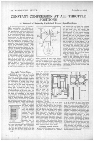
A ROTATING sleeve-valve engine is shown in specification No. 284,988, by S. S. Allwi I, of New York State. Each sleeve has a tapering part at its upper end which forms a gas-tight joint against a corresponding tapered part in the cylinder proper. Ports for inlet and exhaust are formed in both sleeve and cylinder. The sleeves are pressed downwards by means of spring-actuated rollers to compensate for wear. Worm gearing rotates the sleeves. A cover provided with a piston ring is used to form a gas-tight joint inside the sleeve, so as to prevent the pressure of the explosion from tending to lift the sleeve. In the face of the references to previous inventions made by the inventor and what we have seen before in rotary sleeve engines, it is not-easy to se any striking novelty in the invention, which; in this respect, is like many others for which patents are granted.