


THE LATEST YORKSHIRE STEAM WAGON.
Page 30
If you've noticed an error in this article please click here to report it so we can fix it.
A Résumé of Recently Published Patents.
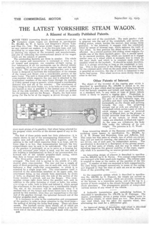
SOME VERY interesting details of the construction of the Yorkshire steam wagon are disclosed in specification No. 201,963, by W. J. Lewin and Deighton's Patent Tube and Flue Co., Ltd. The latest model wagon of that make, we may remind our readers, is of the live-axle type, and was described by as some time ago. This specification is of value as showing the objects of the inventors and manufacturers, and also as indicating the constructional details of the wagon which are the subject of patents. The outstanding features are three in number. The whole of the engine and transmission is contained in what. IS, to all intents and purposes, one complete oil-tight casing, so that lubrication of all the mechanism can be effected merely by supplying oil at two pointsthe engine case and the rear axle case: • The suspension of the engine-gearbox unit in the frame is designed to facilitate the transmission of the stresses of the torque and thrust over a considerable portion of the main frame. The unit is three-point suspended, and the main cross-member which supports the rear end is attached to the longitudinal members of the main frame through the medium of widely spread wings or gussets, which extend a.considerable distance fore and aft of the member. • The attachment, of these wings to the main frame, too, is by bolts or rivets, which are located as near as possible to the neutral axis of the section of the side members, the webs only of which are drilled for the purpose, and not the flanges. finally, the feed-water pump 1,'Ior the beiler of the wagon) is driven through a con
stant-mesh pinion of the gearbox, that wheel being selected for the purpose which revolves at the slowest speed of any in the box.
The first of these points needs but little elaboration: it is clearly shown in one of the accompanying illustrations. The engine case and the gearbox are bolted together, and the opening in the wall which separates them is so large, and its lower, edge is so low, that communication between the two compartmeats may be said to be unhindered. The rear end of the gearbox is prolonged, so as to serve as a housing for the only universal joint which is used, and the rear end of this housing is hemispherical,' so that it can accommodate the forward end of the tubular propeller-shaft casing, which does duty as torque and thrust member.
The three-point suspension of the main unit is simply arranged. The front end is carried in the middle of a substantial plain cross-member. The rear end has a couple of pairs of short projecting arms, one at each side each of which embraces a deep cradle-like cross-member, to which it is attached by a single large bolt. The cross-member itself is attached to the main-frame members at its upper ends, the attachment being, as has already been mentioned, by rivets or bolts, so disposed that only the web of the section of the frame member is pierced, and not the flanges. This crossmember sweeps right down below the gearbox unit, and, in addition to the plain fastening of rivets or bolts, has extensive wings or webs, both in front and behind it, which spread the attachment to the main frame over a considerable length. The aim of the inventors will be understood, when it is realized that all the torque and thrust forces have to be supported by this member, since they are transmitted to the rear end of the gearbox through the spherical forward end of the tubular propeller-shaft casing. It is necessary to refer to the construction and arrangement of the gearbox in order to draw attention to the third point— the method of driving the boiler feed pump. There are three speeds. The layshaft carries three wheels, all of which are securely keyed to that shaftThe largest wheel is at the forward end of the box, and is constantly in mesh with a pinion B46
on the rear end of the crankshaft. The main gearbox shaft is spigoted into the end of the crankshaft, and carries one sliding pinion, which, besides the neutral, may occupy three positions. In the foremost, it "engages with the Crankshaft wheel by means of internal cogs, which embrace the teeth Of that wheel. In that position the direct drive on top gear 18 afforded. In a central poSition this sliding wheel engages the middle one of the three layshaft gears; this is second speed. In its rearmost position, dogs which are formed on it engage similar ones on a wheel which is normally free to rotate on the main shaft, and which is in constant mesh with the smallest wheel on the layshaft, It should be noted, therefore, that it is always revolving so long as the crankshaft is' turn ing. This is the position of the sliding wheel for first speed. On the constant-mesh wheel on the main shaft, however, there is mounted An eccentric, the clip of which is connected to the boiler feed pump. This wheel revolves more slowly than any other in the box.
Other. Patents of Interest.
The object of the inventor of the tipping gear which is described in specification No. 179,949 is • stated to be the designing of a gear which shall be capable of being turned out from the factory complete and tested, and ready to be fitted, as a standard unit, to any make or type of motor vehicle which is likely to require a tipping gear. Production in quantity and cheaply is thus facilitated. The gear is of the hydraulic type, the cylinders and their rams being disposed horizontally on .the chassis and pointing 'towards the rear. The projecting plunger rod or rods are attached to a cross-shaft which carries a pair of rollers which engage two cams, or inverted ramps, so shaped that, as the plunger is forced outwards from the cylinder, the body of the vehicle, to which these ramps are attached, is lifted and tipped. As the rams are withdrawn the body falls under the influence of its own weight. The patentee is L. G. Wood.
Some interesting details of the Ransome swivelling mobile workshop crane appear in specification No. 202,034, by P. A. H. Mossay and Ransomet' Sims and defferies, Ltd. This crane has four pairs of wheels, two of which are swivelling, and are used for steering ; the others do not swivel, but are driven, one of each pair, by independent motors. The specification is devoted to a description of the pivotal mounting of all four pairs of wheels, and the way in which that mounting improves the general stability of the crane, especially when it is manceuvrmg on uneven ground surfaces.
An interesting design of silencer is described in specification No. 202,013, by 0.. B. Davies. Two conical compartments are arranged with their small-ends together. The exhaust pipe is coupled to them at the centre, at the junction of the two parts. A number of slats are mounted in both compartments, the slats being arranged successively in zones of the casing, and disposed so that the slats of each set are at an angle to those of the preceding one.
In the suspension system which is described in specification No. 189,762, by I. Dumont,the wheels are carried on stub axles mounted in casings, which are pivotally connected, at the bottom, to a transverse spring, and at the top to a system of levers coupled to the chassis through the medium of shock absorbers, The arrangement permits of independent vertical motion of any wheel of the vehicle.
A hydraulic transmission gear embodying turbines is described in specification No. 179,179, by H. Fottinger. The engine, presumably, drives a pump which supplies water to the turbine wheels, of which there are two. One drives one rear road wheel, and the other the opposite wheel, thus eliminating the need, for a differential gear.
An improved design of detachable road wheel is described'. in specification No. 190,704, by Rudge-Whitworth, Ltd.