


EQUIPPING A COACH FOR WIRELESS RECEPTION.
Page 19
If you've noticed an error in this article please click here to report it so we can fix it.
In Connection with the Three-valve Regenerative Receiver Described in these Articles we Discussed Radio Inductance. This Subject is Continued in this Instalment.
WE POINTED out last week how innuctance in a radio circuit was exactly analagous to inertia in mechanics, and we saw how the frequency of oscillation or alternation had a very close bearing on the effect of a given amount of inductance.
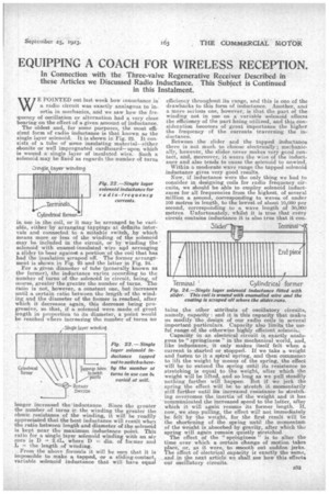
The oldest and, for some purposes, the most efficient form of radio inductance is that known as the single layer solenoid. It is shown in Fig. 22. It consists of a tube of some insulating material--either ebonite or well impregnated cardboard—upon which is wound a single layer of insulated wire. Such a solenoid may be fixed as regards the number of turns
in use in the coil, or it may be arranged to be variable, either by arranging tappings at definite intervals and connected to a sUitable F witch, by which means more or less of the winding of the solenoid may be included in the circuit, or by winding the solenoid with enamel-insulated wire aed arranging a Slider to bear against a portion ofthe coil that has had the insulation scraped off. The former arrangement, is shown in Fig. 23 and the latter in Fig. 24. For a, given diameter of tube (generally known as the former), the inductance varies according to the number of turns of the solenoid in circuit, being, of eourse, greater the greater the number of turns. The ratio is not, however, a constant one, but increases until a certain ratio between the length of the winding and the diameter of the former is reached, after which it decreases again, this decrease being progressive, so that, if a solenoid were made of great length in proportion to its diameter, a point would be reached: where increasing the number of turns no
longer increased the'induotance. Since the greater the number of turns ir. the winding the greater the ohmic resistance of the winding, it will be readily appreciated that the best inductance will result when the ratio between length and diameter of the solenoid is kept near the maximum inductance point. This ratio for a single layer solenoid winding with an air
core is D 2.4Ie where D diii.. of former and L = the length of winding.
• From the above forrnrula it will be seen that it is impossible to make a tapped, or a sliding-contact, variable solenoid inductance that will have equal
efficiency throughout its range, and this is one of the drawbacks to this form of inductance. Another, and a more serious one, however, is that the part of the winding not in use on a variable solenoid affects the efficiency of the part being utilized, and this consideration becomes of great importance the higher the frequency of the currents traversing the inductance.
Between the slider and the tapped inductance there is not much to choose electrically ; mechanically, however, the slider never makes very good contact, and, moreover, it wears the wire of the inductance and also tends to cause the solenoid to unwind.
Within a moderate wave range the tapped solenoid inductance gives very good results. Now, if inductance were the only thing we had to consider in designing coils for radio frequency circuits, we should be able to employ solenoid inductances for all frequencies from the highest; of several million a second, corresponding to waves of under 100 metres in length, to the lowest of about 10,000 per second, corresponding to a wave length of 30,000 metres. Unfortunately, whilst it is true that every circuit contains inductance it is also true that it con
tams the other attribute of oscillatory circuits, namely, capacity : and it is this capacity that makes us modify the design of our radio coils in several important particulars. Capacity also limits the useful range of the otherwise highly efficient solenoits
Capacity in an electrical circuit is exactly analogous to " springiness " in the mechanical world, and, like inductance, it only makes itself felt when a current is started or stopped. If we take a weight and fasten to it a spiral spring, and then commence to lift the weighs by means of the spring, the effect will be to extend the spring until its resistance to stretching is equal to the weight, after which the weight will be lifted, and so long as we pull steadily nothing further will happen. But if we jerk the spring the effect will be to steetch it momentarily still further until its; increased resistance to stretching overcomes the inertia of the weight and it has communicated the increased speed to the latter, after which it will again resume its former length. If, now, we stop pulling, the effect will not immediately be felt by the weight, for the first result will be the shortening of the spring until the momentum of the weight is absorbed by gravity, after which the spring will again remain quietly stretched The effect of the " springiness" is to alter the time over which a certain change of motion takes place, or, as it were, to smooth out sudden jerks. The effect of electrical capacity is exactly the same, and in the next article we shall see how this effects our oscillatory circuits.