


Patents Completed.
Page 24
If you've noticed an error in this article please click here to report it so we can fix it.
Valve Grinding Device-An Adjustable Seat—Straker Engine Construction.
H. W. PEIRtc, No. 2571, dated 31st January, 1913.—This invention relates to a device for facing valves having coned seatings; primarily it consists of a block provided with a conical roughened recess. To this block is attached a cylindrical member through which passes the valve stem. Steel balls are provided inside this member and sleeves having conical ends bear on the balls. The end of the cylinder is screwed to acdommodate a plug. It will be seen that upon screwing or unscrewing the plug, the balls, by means of the coned sleeves, will be able to adapt themselves to the valvestems of varying diameters.
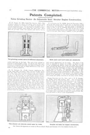
W. 31. COWARD, No. 27,140, Cognate Application No. 27,140, dated 26th November, 1912, and No. 11,432, dated 16th May, 1913.—This invention relates to the valve mechanism of the slide-valve type in internal-combustion engines. As shown in the drawing, two semi-circular sleeves are provided between the inner face of the working cylinder and the inner extension of the cylinder head. These sleeves are accommodated with ports, the left-hand side being the inlet valve and the right-hand side the exhaust. Each sleeve is provided with arms which extend through slots in the cylinder and are actuated by means of cams on the half-time shaft. The sparking plug is arranged in the cylinder head in the usual manner and packing rings which bear on the inner surface of the semi-circular valve members are also provided to prevent leakage of the gases occurring owing to the pressure inside the cylinders.
W. A. LAMPLUGH, No. 28,096, dated 5th December, 1912.— Both the seat proper and the back rest, as described in this specification, are adjustable. The seat proper is mounted on slides so that it, can be adjusted backwards or forwards by means of a nut and screw. The back of the seat is held on arms which extend forward and engage slots in the framework of the seat, there being a number of slots provided so that several adjustments can be made. The slope of the back is adjusted by means of a roller, as shown in one of the accompanying figures, which lies under the inclined arms carrying the hack, and by its movement backwards or forwards varies the inclination of these arms and therefore of the back of the seat. The controlling handles for both adjustments are mounted on telescopic members. A particular advantage of this construction is that, owing to the seat proper and the back being separate, the vibration transmitted to the passenger is very much reduced since only the seats proper are rigidly connected to the body of the vehicle.
BRAZIL STRAKER AND Co., Ian., and A. H. R. FEDDEN, NO. 23,951, dated 19th October, 1912. The accompanying drawing shows an internal-combustion engine in which the cams and tappets operate in an oil-bath. The crankcase contains a pocket through which the camshaft extends and which is provided with a pipe along the bottom to supply oil to the chamber. This supply may be drawn from the ordinary system for supplying the crankshaft bearings. The oil-bath is extended to enclose the lower end of the valve tappets by means of a plate bolted on the outside of the casing, and an overflow pipe is provided to draw off excess oil from this bath and return it direct to the crankcharnber.