


PATENTS SUMMARIZED.
Page 22
If you've noticed an error in this article please click here to report it so we can fix it.
A Detachable Chain Non-skid.
E. M. EnoIles, of 20, Humboldt Street, Bradford, describes a simple type of chain non-skid in his patent specification No. 109,553. He utilizes a number of separate and independent chains round the wheel, .and attaches each to a Ushaped clamp of steel which is secured to a spoke of the wheel. The Crangesilent is clearly exelnplified in the drawing which we reproduce. The clamp is drilled through both its ends for the reception of a bolt. When it is desired to use the non-skid, the nut of each bolt i.s pemoved, the bolt slipped out of the hole and the chain placed into position, as shown in the drawing; the bolt is then replaced and the nut.screwed home.
Exhaust-heated Vaporizer.
The provision of a vaporizer which requires the minimum of fittings has been the aim of A. T. Salisbury-Jones, of Hyde Park Gate, South lien ington, arid he describes the result of :this efforts in specificatiott No. 109,517. It takes. the form ef .a small casting, internally cored and illsbed so that the exhaust gases pass through it in one direction, while the explosive mixture, separated from the exhau.t by suitable walls, traverses it in a direction at right angles to the path of the exhaust gas. This casting is designed to fit between the flange on the carburetter and the corresponding one on the induction pipe, to which the carburetter would, in normal circumstances, be bolted.
Two views are shown in the drawing -which we reproduce on this page4 one shows a horizontal section through the vaporizer itself, and illustrates the arrangement of the various passages ; the other is an elevation of the carburetter and induction pipe with the vaporizer in position between the two. In order to increase, to some extent, the hea,ting surface of the vaporizer, the central passage of the three through which the exhaust gases pass is made somewhat deeper than the casting itself, so that it projects slightly into both the induction pipe arid into the carburetter delivering branch.
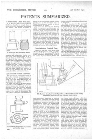
Petrol-electric Control Gear.
Patent No. 109,529, which is the joint effort of the Daimler Co., Ltd., of Coventry, and of W. F. Lanchester, 53, Tingley Road, Edgbaston, Birmingham, concerns the control of petrol-electric chassis; and more particularly that type in which a series-wound generator provides current for two or more series-wound motors, and in which the motors are used for driving independently wheels or endless-track chains, one on either side of the _vehicle. In such a chassis, when one motor only is drawing current, as, for example, when one motor and its corresponding road wheel is stopped while the other continues to drive, so as to facilitate steering, there is a risk of the operating motor being supplied with an excess of current, with resultant damage. This invention has for its object the safeguarding of generator and motors from this risk.
On reference to the drawing, which we reproduce herewith, three hahd-levers will be noticed. Of these, the central one' controls the generator brushes, the others the right lord left-hand motors respectively. The connections between these levers and their respective ,brush-operating mechanisms is quite nOrmal, except for the following, which forms the subject of the patent.
A shaft mounted in the quadrant bracket carries a differential gear. The two sun-wheels of this gear are attached to levers, at the bottom end of which are cam rollers. The rollers bear on heart-shaped cams -which are formed on the bosses of the :two motor-controlling, levers, so that any movement of either lever causes a corresponding movement of the differential sun-wheel on the same side. The spindle of the star pinion, for there is only one, is fukrumed on the shaft which carries the sun-wheels, and forms a lever, the bottom end of which is coupled, by means of a link, to 'the generator-controlling lever. In the drawing, three positions of the motor levers are shown : forward, neutral and reverse. The generator lever is in its neutral position when right back. On examination it will be seen that the came are designed to have full effect when the motor levers are in the central, or neutral position. When moved together to neutral, they will force the two sun-wheels, which will carry with them the star-wheel and spindle' to move in an anti-clockwise direction. This will have the effect of moving the generator lever to the neutral position. Movement of one motor lever to either of its two operating positions, will, owing to the consequent release of its corresponding sun-Wheel, allow of the generator lever being moved the half of its full motion. Movement of both motor levers to operating positions, whether both forward, or, both rearward, or one in either direction, will completely
release the generator lever. This action follows from the principle of the working of the differential gear.
. By these means it is ensured that (a) with neither motor taking Current the generator cannot be made to produce s (la) with only one motor working, the generator can only be caused to produce s-ufficient current for the one; and (c) with both motors calliog for current, full power is available from the generator.
•