


IMPROVING AND IMPROVISING TOOLS.
Page 33
If you've noticed an error in this article please click here to report it so we can fix it.
A Number of Useful Ideas from Our Driver and Mechanic Readers.
MEE SOLDERING iron is not
bivari
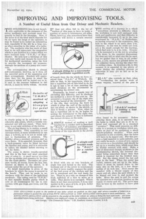
ably applicable to the purposes of the motor mechanic, and recourse must frequently be had to the blowpipe. Now, if the latter is of the kind which depends for its air upon the lungs of the operator, it may be found to he rather an exhausting tool, especially if the job be a king one, as when sweating in the tubes of a radiator. The mechanic who has work of that kind to do will appreciate the suggestion which is put forward in a letter which we have received from " T.W .H.," of Manchester. He tells how a blowpipe of this type may easily and cheaply be converted for mechanical operation, using the foot to provide the necessary air pressure, through the medium of a pump and reservoir.
The accompanying sketch is almost self-explanatory, showing, as it does, all the essential parts of the apparatus and their arrangement Readers will appredate that, for the pump to stand the treatment which will be meted out to it, if used in the manner indicated in the sketch, it must be fairly robust. Its stem is clearly going to be subjected to considerable side strain, which a weakly constructed rod will not stand. That, however, is our only criticism of the device.
The air bag shown is, in reality, a small football bladder. This, according to our correspondent, is more satisfactory in use than a bellows, as it is not so much subject to fluctuations of pressure. The bladder gives a constant pressure and an even flame. It is essential, however, that a back-pressure valve be fitted between the bladder and pump, and it is advisable to inflate the bladder before starting to use the flame.
The pump is shown treadle-operated and this is the best and most practical way of using it. A small spring provides for the up stroke, and pressure by the foot for the down stroke. Excessive air pressure would, of course, burst the bug, but, located as shown in the sketch, it is always under the eye of the operator.
No detail description is given of the brackets by which the pump is secured to the bench. They can be made in accordance with the ideas of the individual mechanic. The tubing used by "T.W.H." is that metallic flexible piping which is sold at all ironmongers for use in connection with gas rings, gas irons, and the like. IT does not often fall to the lot of readers of this page to have to make a number of parts to micrometer, all alike. Those, however, who sometimes have that experience will derive a certain amount of benefit from the tip which we have received from " P.A.G.," of Wisbech. He tells us that, in his experience, when he has a repetition job of this kind to do, he is apt to lose a lot of time counting the small divisions on the micrometer in ascertaining the correct one.
Eventually, he found a simple way of obviating this difficulty, and he discloses his method in a letter he has sent us. He procured a fountain clip of the right size to fit the barrel of the micrometer. Part of the clip, that carrying the knob by which it grips the wall of the pocket, he has cut away, as shown in the sketch, so that it forms a pointer. Now, when he has a repetition job to do, he begins by setting the micrometer to the right size, and places the pointer so that it indicates the correct division on the scale.
A SIMPLE method of making a wall
bracket for a ratchet drill is described by " H.A.C.," of Leicester, and illustrated by one of the accompanying sketches. An old clamp of the type shown in the sketch 's fitted with one or two brackets of angle iron and bolted to the wall. The business end of the screw is countersunk so that it more readily engages the point of the feed screw of the ratchet, and the job is completed and the tool ready for use. There is, as a rule, on clamps of this kind, sufficient of a face to serve as a table. That shown is so equipped. Where there is not that convenience, it is an easy matter to fit a piece of fin. or I-in. boiler plate an to the clamp. THE cutting of a keyway in a wheel
sometimes presents a difficulty when the workshop is not well equipped with tools and appliances, and that difficulty is considerably increased if, as in the case mentioned by " H.A.13.," of Rotherham, as having occurred in his experience, the_ hole in the wheel is no more than fin. diameter. In his case he could not even get a file small enough for the keyway, which had only to be it in. wide. Eventually he managed to do the job by grinding a file down to the required dimensions. He does not tell us what size file he used, but we gather that it was, in all probability, a fin, square one ground down on two adjacent faces, leaving the other two as cutting edges. In treating a file in this manner it is essential to use plenty of water during the grinding process as otherwise it may get so hot as to be softened.
also reminds us that, when overhauling the motion work of steam wagons, renewal of the pins is often found to be necessary. Before ordering these pins, it is essential that the holes in which they are to fit be rebored and reground all to a standard "oversize." This work presents no difficulty in a garage or workshop which possesses as part of its equipment a small spindle-grinding machine. When such equipment is not available, then the holes will have to be lapped out. For this purpose a lead mandrel is quite suitable, and can easily be made. A piece of fin. square bar serves as a foundation, and should be set up in a wooden base, which must then be thickly covered with sand. Make a pair of sheet-steel clamps, as shown in the accompanying sketch, the internal diameter being somewhat larger than that which is required for the finished mandrel. Set the clamp round the bar and pour in the lead. When the metal has cooled, remove and set up in the lathe, where it must be turned down to the same size as the hole, or a few thousandths of an inch less. Next smear the mandrel with a liberal supply of fine emery and oil, place the part which is to be lapped out over it, and re-start the lathe. Move the part to and fro across the mandrel as it revolves, keeping up the supply of emery and oil. The parts may then be-sent tp the makers to have pins fitted.