


A New and Larger Ensign.
Page 14
Page 15
If you've noticed an error in this article please click here to report it so we can fix it.
For Four-ton Net Loads. Substantial Construction and Sound Design.
Final
Drive by Worm.
The three-ton Ensign was placed on the market at a time when the scarcity of vehicles of that size was most acute, and when users were at their wits end to arrange for the transport of material; it met with a correspondingly enthusiastic reception. For cur part, in conformity with our general usage and, owing to the above conditions, with an increase of our usual anxiety to place early particulars of new models before our readers, we investigated its value and presented a critical description in the issue of 3rd December of last year.
" C,M." First Out with the New Models.
The fact that a larger model was on the way has been known to us for some time and at the earliest possible moment We obtained detailed particulars, the publication el which, however, has, for reasons which we may not divulge, been withheld. We are at length, however, able to describe this chassis and, consistently with our usual attitude with respect to new models, we have pleasure in giving our readers the benefit of our first-hand and prior knowledge and authoritative criticism. As a result, they form that section of the public first to hear of this Cr any new development, with the consequent advantage of acquiring facilities for placing early orders for new vehicles with the backing of our description and opinions to guide them as to its suitability for any purp0e they may have in view.
Superabundance of Strength. Long Wheelbase.
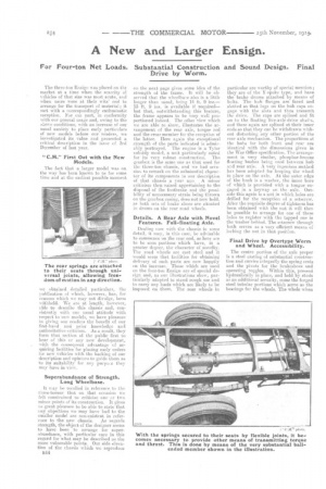
It may be recalled in reference to the three-tonner that on that occasion we felt constrained to criticise one or two minor points of its construction. It gives us great pleasure to be able to state that eny objections we may have had to the smaller model are non-existent in refer ence to the new chassis. As regards strength, the object of the designer seems to have been to arrange for superabundance, with particular care in this regard for what may be described as the more vulnerable points. Our side elevation of the chassis which we reproduce B44 on the next page gives some idea of the strength of the frame. It will be observed that the wheelbase also is a little longer than usual, being 14 ft.
13 ft. 9 ins, is available if required— but that, notwithstanding this feature, the frame appears to he very well proportioned indeed. The other view which we are able to show, illustrates the arrangement of the rear axle, torque rod and the cross member for the reception of the latter. Here again the exceptional strength of the parts indicated is admirably portrayed. The engine is a Tylor subsidy model, a unit particularly noted for its very robuet construction. The gearbox is the same one as that used for the three-ton chassis, and we had ots.e..asion to remark on the substantial character of its components in our description of that chassis a year ago A minor criticism then raised appertaining to the disposal of the footbrake and the possibility of unnecessary strain being thrown on the gearbox casing, does not now hold. as both sets of brake shoes are situated in drums on the rear road wheels.
Details. A Rear Axle with Novel Features. Full-floating Axle.
Dealing now with the chassis in some detail, it may, in this case, be advisable to commence on the rear end, as here are to be seen portions which have, in a greater degree, the character of novelty. The road wheels are cast steel and it would seem that facilities for obtaining delivery of such parts are now happily on the increase. Those which are used on the four-ton Ensign are of special design and, as our illustrations show, particularly adapted to stand rough use and to carry any loads which are likely to be imposed on them. The rear wheels in particular are worthy of special mention; they are of the Y-spoke type, and have the brake drums attached by means of bolts. The huh flanges are faced and slotted so that lugs on the hub caps engage with the slots and thus transmit the drive. The caps are splined and fit on to the floating live-axle-drive shaits, and these again are splined at their inner ends so that they can be withdrawn without disturbing any other portion of the rear axle mechanism. The proportions ot the hubs far both front and rear are identical with the dimensions given in the War Office specification, The arrangement is very ssmilar, phosphor-bronze floating hushes being used between hub and rear axle. A very ingenious method has been adopted for keeping the wheel in place on the axle. At the outer edge of the bush is a washer, the inner bore of which is provided with a tongue engaged in a keyway on the axle. Outside this again is a nut in which holes are drilled for the reception of a setscrew. After the requisite degree of tightness has been obtained with the nut it will then be possible to arrange for one of these holes to register with the tapped one in the washer behind. The setscrew through both serves as a very efficient. means of locking the nut in that position.
Final Drive by Overtype Worm and Wheel. Accessibility.
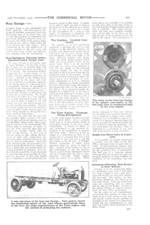
The centre portion of the axle proper is a steel casting of substantial construction and carries integrallythe spring seats and the pivots for the brakeshoes and operating toggles. Within this, pressed hydraulically in place, and held by studs as an additional security, come the forged steel tubular portions which serve as the bearings for the wheels, The whole when
complete forms a very aubstantial and sound structure. The final .drive is by means of overhead Worm and wheel with differential gear of the bevel type, and we note the provision of substantial ball and thrust bearings whenever these are necessary, the whole of the gearing being carried 'by one casting which forms the cover for the rear axle casing. After withdrawal of the axle shafts it is, ef course, possible to lift this cover and with it the worm, wheel, and differential, exposing them for examination.
Rear Springs on Universal Joints. Spherical-ended Torque Tube.
We have referred to the spring seats as being identical with the axle casing, bet it must not be inferred from this thtt the torque and thrust are taken up by the springs. The attachment of these component is a special feature of the chassis and has received particular at tention. Instead of the springs being belted direct .to the seats, each rear spring is carried an a bracket connected to the spring seats by a universal joint. Ceusequently freedom of movement • is all wed in any direction with the result that the springs are called upon only ti. perform the function of alleviating the stresses due to road shocks, -The torque atul thrust are taken by a very substantial tubular ball-ended torque rod,. the rein: end of .which is bolted to the axle caeing.' the fore end being housed, in a special cast-steel cress member. The ball end of the torque rod serves to enclose a eeiversal joint of the two-ja.w type, the latter beings notable for the special auto-nettle msans of lubrication.
13etween this joint and the rear axle the propeller-shaft, carried at its front end by ball and thrust bearings, runs to a horizontally sliding joint which transmits the power to the worm spindle. The sliding joint is necessary,of course, in case the front universal joint does not happen to coincide exactle with the centre ef the bearing. In the event of this not being so and without the provision of some such construction, unnecessary strain would be thrown on the pins of either or both joints. From this front universal joint and proceeding owe more towards the front of the chassis, we have a short shaft and another joint immediately behind the gearbox. It is evident that the possibility of non-alignment of parts has been kept carefully in View, and the provision' of this joint should serve effectually to guard against any loss
of power owing to this cause. It might be as well to point out that soloing as the parts are in line there is, as a matter of fact, no loss of power. as a result of the intervention of a joint of this nature, if alignment is disturbed, the joint saves more power than it uses.
The Gearbox. Inverted Cone Clutch.
The gearbox, as we have previously remarked, is precisely the same as that employed on the three-ton chassis. It provides four speeds and reverse and is remarkable for its abort sturdy shafts and substantial width and depth of its gears. Between gearbox and engine comes the usual doubly-jointed clutch shaft, and we eventually arrive at the clutch itself. This is of the .inverted cone type, the spring being arranged so_ that all • the thrust is self-Contained excepting during the time in which the clutch pedal is pressed down and the component itself is not engaged. It has not been deemed necessary to make the clutch spying very accessible for occasional adjustment as it issedesigned that any difference of length -occasioned by wear of the chiteh lining willetetshave any appreciable effect on the strength of the spring. It is operated through the, Mediums of a clutch fork on the end of which are ball bearings inn contact, when the clutch' is being disengaged; with a flange on the inner member. The feature, to which We referred in our description of the three-tonner, of these bearings being out of contact except when they are actually in use, has been retained on the new =it'd.
The .Tylor Engine. Thorough Oiling Arrangement. •
To the Tylor engine we heed tint refer in very _much detail. It is a subsidy model and, as we have already stated, is particularly notable for its very -robust construction. A feature to which we gave ..prominence in our previous description is the accessibility of magneto and water pump. These are driven by means of a :cress-haft in front of the t, and so arranged that this is the first thing to meet your eye as you lift the bonnet on the off side. .A MandelHobson carburetter is fitted, being operated either by means of hand or foot. Another point worthy of note is the construction of the fan bracket. This is a particularly substantial feature and so arranged that the belt is automatically tensioned within certain limits by means of a spring. When
these limits are exceeded it is possible to take out a link of the-belt owing to the fact that the Whittle leather jointed belt is provided. The oiling arrangement has been very .carefully thought out and the filler is low down on the bottom half of the crankcase on the off side of the engine_ It is 'arranged on a similar principle to that very common on rear axles, serving as an overflow device in addition to being a filler orifice. Criticism may he levelled.at this on account of its apparent inacieessitility. but we are assured that in.-oractice there has been found no causefor complaMt. On the other hand, the -oil filter, which is contained in a receptacle on the near side 'of the engine, is very accessible.
Ample-size Hari cL-holes in Crank case.
As is essential in engines constructed to comply with the needs of the War Office, crankcase doors of ample size are fitted. In this -particular instance they are fastened by means of the device used for the smoke-box doors Of locomotives. The • half turn of a hand-nut 'releases them and they can be removed, and very adequate facilities are then availablefdr inspection of the connecting rods and shaft.
Ackermann Steering. Both Brakes in Rear Wheels.
Steering is of the stereotyped icam ; the Ackermann type with a hall-ended rod from column to front axle and a cross rod behind the axle with substantial jaw-ends. The brakes, we have previously intimated, take effect