


Powered Steering Mechanism
Page 68
If you've noticed an error in this article please click here to report it so we can fix it.
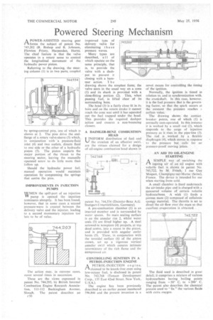
A POWER-ASSISTED steering gear I--kforms the subject of patent No. 745,202 (R. Bishop and R. Johnson, Flowton Priory, Harpenden, Herts). The chief feature is that the valve operates in a rotary sense to control the longitudinal movement of the hydraulic power piston.
Referring to the drawing, the steering column (I) is in two parts, coupled
by spring-centred pins, one of which is shown at 2. The pins drive the endflange of a rotary valve-sleeve (3) which, in conjunction with -a pressure-fluid inlet (4) and two outlets, directs fluid to one side or the. other of a hydraulic piston (5). The piston imparts the major portion of the thrust to the steering sector, leaving the manually operated screw to do little more than follow up.
Should the hydraulic power fail, manual operation would • maintain operation by compressing the springs that centre the pins.
IMPROVEMENTS IN INJECTION PUMPS
WHEN the spill-port of an injection VY pump is opened the injection terminates abruptly. It has been found, however, that in some cases ,a second pressure-wave is created between the delivery valve and the injector, leading to a second momentary injection toci late to be of value.
The action may, in extreme cases, occur several times in succession.
These are the views expressed in patent No. 744,293, by British Internal Combustion Engine Research Association, 111-112 Buckingham Avenue, Slough. The patent describes an c30 drawing shows the simplest form; the valve seats in the usual way on a cone (/) and its shank is provided with a close-fitting portion (2). This, when passing fuel, is lifted clear of its surrounding bore.
The head (3) is a fairly close fit in its bore and on the return stroke it cannot reach the cone scat until it has squeezed out the fuel trapped under the head. This provides the required dashpot action and ensures a non-bouncing closure.
A DAIMLER-BENZ COMBUSTION HEAD
UNIFORM distribution of fuel and the creation of an effective swirl, are the virtues claimed for a design of oil-engine combustion head shown in
patent No. 744,554 (Daimler-Benz A.G. Stuttgart-iintertUrls helm, Germany).
A pre-combustion chamber (1) is an inserted member and is surrounded by water spaces. Its main sealing surface is on the annular rim 2, whilst water seals (3) are fitted higher up. . A steel screwed-in nosepiece (4) projects, at top dead centre, into a recess in the piston, and is provided with angular outlet bores (5). These, in conjunction with the toroidal surface (6) of the piston crown, set up 'a vigorous vertical annular swirl which ensures intimate intermixture of the rich flame and the compressed air.
CONTROLLING IGNITION IN A PETROL-INJECTION ENGINE A PETROL-INJECTION engirre, ri• claimed to be knock-free even using low-octane fuel, is disclosed in patent No. 742.768 (Texaco Development Corp., 135 East 42nd Street, New York, U.S.A.).
The engine has been previously described in an earlier patent numbered 596,846 and the present invention is a novel means for controlling the timing of the ignition.
Normally, the ignition is timed in relation to, and in synchronization with, the crankshaft. In this case, however. it is the fuel pressure that is the governing factor, so that the spark occurs at the moment the pressure reaches a ceftain value.
The drawing shows the contact. breaker points, one of which (I) is normally cam-operated. In this instance it is worked by a small rod (2), which responds to the surge of injection pressure as it rises in the pipe-line (3). The rod is worked by a flexible diaphragm (4), which moves in response to the pressure but calls for no pressure-proof moving joints.
AN AID TO OIL-ENGINE STARTING
ASIMPLE way of enriching the ingoing air of an oil engine with volatile fuel is shown in patent No. 745,722, by M. Frisch, 1 rue Guy Moquet, ChamPigny-sur-Marne (Seine), France. The device is intended for use when starting from cold.
A small chamber is fixed underneath the air-intake pipe and is charged with a measured volume of certain volatile hydrocarbons. A wick (1) feeds a porous mass (2) composed of cellulosic spongy material. The throttle is set to direct the air flow over the mass so that excellent evaporation is obtained. .
The fluid used is described in great detail; it comprises a mixture of various hydrocarbons having boiling points ranging from —50° C. to +200° C. The patent also describes the chemical process used to " fix " the various fluids with extra owygen.