


A "No-knock" Injection System
Page 58
If you've noticed an error in this article please click here to report it so we can fix it.
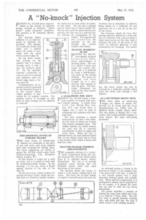
PATENT No. 651,438 shows improvements in The Control of .injection pumps, claimed to eliminate " diesel knock" under full-power conditions. The patentee is W. Johansen, Skaum, Norway.
The drawing shows sufficient of an injection pump to illustrate the principle. The plunger (1) is centrally bored, and slides over a control sleeve (2) which is provided with the usual helical control edge (3).
On the down stroke, fuel arriving via the annular belt 4 is drawn through ports 5 and . 6 into the pressure space (7) On the upstroke, injection commences as soon as port 6 is covered and continues until the helical edge meets a bypass port (8).
Commencement of injection is clearly governed by the elevation of port 6 in the control sleeve, whilst quantity is controlled by its angular rotation. The exterior control is arranged so that both of these settings can be adjusted as required.
D1RT-PROOFING PIVOTS OF ENDLESS TRACKS
THE track pivots of crawler-type vehicles are vulnerable to the entry of grit and water, and many schemes have been proposed for sealing them. The latest suggestions are shown, in patent No. 651,446, which comes from Vickers-Armstrongs, Ltd., Broadway House, London, W.I.
In this scheme, a single pin is used per joint, and it is sealed at both ends by compressed-rubber bushes. in the drawing, I is the pin, which is keyed against rotation to the side of the link (2).
On the inner faces, rubber washers (3) prevent the entry of dirt, whilst the outside faces arc closed by smaller washers (4), which can be made either of rubber or soft metal. The pin has a tapered end on which seats a metal washer (5); this not only seals the space between nut and pin, but also acts as a pull-up face for limiting the compression of the • rubber. The tapered end also simplifies the assembly of the pin through the various washers and bushes.
SEALING SPARKING PLUGS
PATENT No. 650,797, from Bendix Aviation Corporation, U.S.A. shows improvements in sparking plugs. The aim is to obtain a better seal round the central electrode, and it is achieved by using a lead-borosilicate glass as the sealing medium. The parts are assembled, and then brought up to a temperature high enough to melt the glass. The electrodes themselves are made of the alloy known as nichrome.
A LEAK-PROOF PIPE JOINT PATENT No. 651,499 shows a pipejoint capable of sealing high pressure without leakage. It comes from C.A.V., Ltd., Warple Way, London, W.3, and would seem to suggest that it may be used in connecting fuel injectors with their pipe-lines.
The joint comprises a tapped body-portion (I) and a bolt member (2), both of which are formed with convex abutment faces. The middle member (3), which receives the pipeend (4) is conically countersunk on both its upper and lower faces. When the bolt is ightened down, the mate spherical faces bear on the female cones and so form a line contact which makes a secure and leak-free joint.
TRACTOR-TRAILER STEERING ARRANGEMENTS
THE composite steering of a tractor1 trailer combination forms the subject of patent No. 651,473, which comes from S. A. Adolphe Saurer, Arbon, Switzerland. The aim is to provide automatic trailer steering that will faithfully follow small and rapid deviations of the tractor.
The drawing shows the layout in which 1 is the motive vehicle and 2 the trailer. The latter has its four wheels arranged in steerable pairs, but only the rearmost axle is controlled, its rodwork being linked by a bellerank (3) and ratio-lever (4) to a pin (5) on the rear of the tractor.
The foremost wheels (6) have their steering mutually linked by a track-rod, but are otherwise free, and are given a slight castor-action so that they tend to maintain the path of the front of the trailer in whatever direction it may momentarily be travelling. For revers AN L-,SECTIONED PISTON RING
THE latest ideas on piston-ring design are shown in patent No 651,618, by R. Cross and the Cross Manufacturing Co. (1933),, Ltd., 33, Midford Road, Combe Down, Bath. The ring shown is shaped like a cupwasher, and would probably possess, to some degree, the same self-sealing properties.
An enlarged section is shown in the drawing in which 1 is the cylinder wall, 2 the piston and 3 the ring. It calls for a very narrow groove, but a large clearance between piston and cylinder wall. When used for compression, it is positioned as shown, but if required for an oil scraper, it is placed the other way up, that is, with the cup facing downwards.
The patent describes a method of making the rings from rolled steel strip, A-in. wide by 1/32-in. thick. The redhot strip is passed between forming rolls, and while still hot, the strip is taken round a cold winding mandrel.