


Can the Gearbox Be Improved Upon?
Page 24
Page 25
If you've noticed an error in this article please click here to report it so we can fix it.
Despite Many Attempts to Introduce Mechanical Torque Converters of the Infinitely Variable Type, the Gearbox, Giving Definite Fixed Ratios, is Still Universally Employed
By J. Pickles,
A.M.I.A.E.
FROMthe early days • of the first sliding-pinion gearbox, the phrase, " It is brutal but it works," made by its inventor, has been continually applicable, and in the search for something that is not brutal, countless hours have been spent, and hundreds of patents filed. In spite of this, by far the greater majority of the vehicles on the road to-day. embodies the original principles of the crashtype gearbox, and the only accepted improvement of any great importance has been..the synchro-mesh device.
True, the epicyclic gearbox has found favour for passenger-service vehicles, but, like the " crash " box, a set number of ratios is provided, the selection of any particular one being under the control of the driver.
The requirements of,a perfect transmission are that the torque delivered to the driving axle shall be varied to suit the resistance to the forward motion of the vehicle and that the adjustment to achieve this shall take place automatically. Hydraulic mechanisms have been produced and have achieved partial success, but the efficiency falls oft rapidly with an increase in reduction ratio, and special provision often has to be made to dissipate the heat of the fluid to the atmosphere.
For many reasons, most interest has been centred on the development of a 'purely mechanical transmission, and many have been produced with varying degrees of success. The mechanism for automatic ratio selection is evolved in a comparatively -simple manner. Assuming the engine to run at such a speed that a constant torque is delivered to the input side of the torque converter, the output side is subjected to the resistance to forward motion, termed the road resistance.
The road resistance is easily measured by means of a spring-loaded coupling arranged so that, at slightly less than the maximum engine torque, the driving and driven sides dl the coupling are in a given torsional relationship. Should the road resistance be greater than the engine torque, the coupling springs will be further compressed, and the relative movement of the coupling flanges made to operate the ratio-change mechanism by a suitable linkage.
This, however, is by far the simplest part of the design, and it is with the torque transmitting mechanism that the difficulty arises. Certain principles are accepted as having the necessary requirements from a functional standpoint, and it is the method of operation of these with which it is proposed to deal. An understanding of the difficulties involved in the design of these gears would prevent a great deal of disappointment to enthusiasts who, time after time revamp these basic ideas and anticipate a revolution in the motor industry.
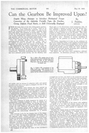
The simplest of all, and the basis of the well-known
Hayes gear, is the friction-face wheel mechanism (Fig. 1) which enjoyed a measure of success on early private cars. This embodies a flywheel having a fiat face. At right angles to the crankshaft is a cross shaft carrying a wheel capable of being pressed on to the flywheel. This wheel is keyed or splined to its shaft in such a manner that it may be slid across the face of the flywheel, thereby varying the effective ratio. Forward or reverse travelling is dependent on the position of running contact on • the flywheel.
This device, depending as it does on the resistance to slip of two contacting wheels, is not capable of transmitting . high power unless components of prohibitive size be used, and grooving the faces is impracticable, because the pinion would have parallel grooves whilst the wheel would be provided with grooves having increasing pitch depending on the radius of the pinion contact.
The Hayes unit was much more satisfactory although more elaborate. In elementary principle, two wheels were
arranged face to face, one fixed to the crankshaft and the other to the case so that it. was restrained from movement, A groove of semi-circular section Was formed in the face of each wheel so that, together, a space of circular crosssection was formed. Mounted on a spider, spliced to the output shaft, were four planet wheels arranged to run in contact with the two grooved wheels.
The planet wheels could thus be made to run in contact with similar relative diameters on both grooved wheels or, by tilting them, on a reduced diameter on one and a larger diameter on the other. To maintain the drive the planet wheels have to be subjected to a high pressure between the two grooved wheels, so that an equal and opposite end thrust is created. To eliminate the need for this, the device was duplicated so that the pressure was carried internally, an analogy being a transmission clutch where the driven plate is subjected to pressure between two revolving discs.
Although at the inception of the device wide publicity was given to it, for some not obvious reason it -did not receive wide acceptance, expense being probably the main factor as there was a good number of expensive components required.
Probably the biggest group of torque converters is those' using ratchets or roller clutches to , transmit the power, and in this lies their great failing. All involve some motion for varying the stroke of the ratchet devices, and they must be accelerated up 'to maximum speed and then decelerated. The mass of the vehicle, like that of the flywheel, tends to move at a constant velocity owing to its inertia.
The ratchet, therefore, engages when it has reaclied only its maximum velocity. This impulsive running is not conducive to passenger comfort unless an impracticable number of ratchets be employed. So arduous is the work imposed on-the ratchets 'that, so far as the writer is aware, a conapletelY satisfactory unit has not yet • been produced. A typical example • of this type of mechanism is found in the wobble shaft gear. In this arrangement, a crankshaft of special forth is journalled in bearings and driven from the engine. The single throw of the crankshaft is so formed that the crankpin, which is of considerable length, is inclined so that, at. one end, it coincides with the crankshaft centre line. A link is journalled at one end to the crankpin, along which it may be moved axially. The more closely it approaches the end coincident with the drive axis .the smaller will be the throw, and the more powerful the push; in other words, the gear ratio is lowered. The link is connected at its other end with a pawl engaging a ratchet on the driven shaft, so that the intermittent link push is conveyed thereto. Four such ratchets axe usually considered for such applications and arranged so that one impulse is given every 90 degrees of driving-shaft rotation.
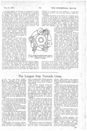
In recent years we have seen, on a famous British" chassis, the Hobbs inertia gear, which sought to obtain the desired result by a somewhat different method to those so far described. The construction—see Fig. 2—is as follows. A pinion is mounted on the driving shaft. At the end of the driven shaft is an arm having two pins formed on it, on which run planet wheels which gear with the sun wheel on the driving shaft, Mounted On the two planet wheels are heavy weights so positioned that rotation of the gears will bring both weights . out to a maximum or a minimum diameter simultaneously—an essential to balance.
Low speed rotation of the-driving shaft causes no similar movement .of the driven shaft, as the weighted planets revolve idly. The tendency for an unbalanced mass, however, is to, revolve about the centre of gravity, so that the !planet journal pin and, therefore, the driven arm, are osciilated backward and forward when the engine speed is sufficient to overcome the road resistance. A free-wheel. arrangement provides for the. power delivery being urndirectional.'
Assuming th9 engine to be running at a constant speed, a stationary driven shaft will cause the weighted planet wheels to revolve rapidly and exert powerful impulses. As the speed of the vehicle and, consequently, the driven shaft increases, that of the planets-will decrease. During this . acceleration centrifugal force, acting on the weights, becomes greater until at 1/1 the weights are heldoutward under this influence and the whole device _ revolves " solidly." A small flywheel is provided at the axle end of the propeller shaft to damp out the vibrations caused during the low-ratio running periods,
Another interesting design, shown in Fig. 3, was the 'subject of a patent within recent years. This unit em ployed a driving pinion and a driven 'planet carrier in which were three planet wheels engaging with the driving sun wheel. Articulated on the planet-wheel pins -were arms carrying further pinions which engage with the planet wheels. By swinging the arms about the planet pins these pinions may have their radius froth the centre varied and springs suitably disposed tend to hold them to the maximum The last-mentioned pinions are formed integrally with a sprocket gear so that rotation of the sun wheel causes
a resulting movement of -the chain gear.
A length of chain is wrapped around the three sprocket gears, one end being anchored to the outer casing.. The other end is connected to a device which permits the effective length to be varied. Thus, changing the length of the chain gives a variation in ratio, although it must be in given steps as the number of operative chain links must be divisible by the number of sprockets, and roughness would undoubtedly occur during the change of ratio.