


Extensible Body for Ambulance Work
Page 40
If you've noticed an error in this article please click here to report it so we can fix it.
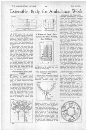
A Résumé of Patent Spedfications that Have Recently Been Published A BODY which, while the vehicle I-1 is stationary, can be considerably extended into " outbuildings," is the subject of patent No. 518,869, by N. Pemberton Billing, London Laboratories, Royal Court Chambers, London, S.W.1. The main purpose is to provide a vehicle suitable for a mobile hospital.
The drawings, two out of 26, give a general idea of the basic principle involved. On each side of the body, panels' (1). already built into light frames, can be swung over on pivots (4) to form the extensions. What were the end walls (5) then become the floor of the additional space. The roof is provided by sliding along one layer of a double roof on the normal body.
The width of the body is increased by pivoted shelving (3), which can be extehded sideways when the side panels have been moved rearward. The extra space thus formed can be used to house stretchers, after being covered by a roof extension (2).
CYLINDER-LINER LOCALIZED COOLING IDATENT No. 518,868 comes from R.
Ricardo, 21, Suffolk Street, London, S.W.1, and shows a means for cooling the hottest spots in a cylinder liner, to prevent distortion at these points.
The liner is located at its lower end in a close-fitting bore, and rests upon a shoulder (3) in the outer jacket. At the upper end the cylinder head presses on the liner at the shoulder (4) where a copper washer is interposed. At the same time the cylinder seals the water space by means of a soft packing washer (2). A series of water-passages (I) connects the jacket with the head, and it is proposed to position these
passages at a steeper angle around the hot spots so as to increase the water velocity at these points.
FUEL INJECTION FOR SLEEVEVALVE UNITS
THE use of fuel injection in a sleeve'. valve engine is proposed in patent No. 518,895, which comes from Bayerische Motoren Werke A.G.,
Munchen, Germany. Although no precise mention is made of the fuel, it is presumably petrol, as injection is made during the suction stroke.
The drawing shows a part section of the cylinder and rotary sleeve (2). The latter is ported at 1 in the path of the air intake (3). The fuel injector (4) is placed to one side of a guide vane (5) which serves to deflect the mixture into a tangential path. The downstream injection, .combined with the heat of the cylinder, is claimed to give excellent atomization of the fuel. AUTOMATIC OR PEDAL-CONTROLLED CENTRIFUGAL CLUTCH
VROM Northern General Transport Co., Ltd., 88, Kingswa,y, London, W.C.2, and G. Hayter, Cemes in patent No. 519,226 a design for a clutch which, although normally engaged -by centrifugal action, can also be operated by ordinary means.
In the drawing, the outer casing is engine-driven, whilst the central faced plate (1) can be gripped or freed in the usual manner. Two presser-plates -(3 and 6) are employed, one (3) being operated by the centrifugal movement of balls (2), whilst the other (6) is pedal operated. A number of hooted detents (5) can, however, hold the plate (6) from movement in an engaging direction.
In the position shown, the engine is stationary and the clutch free. Upon speeding up the engine, the balls move outwardly and engage the presserplate (3). If it be desired to engage the clutch when stationary, the .plate (6) is moved (by the pedal) Slightly to the left; this allows the detents (5) to be pulled inwardly by their springs, after which the plate becomes subject to pedal control in the usual manner. The detents automatically return to the position shown as SOOD as the plate (6) is pushed to the left by movement of the plate (3).
The automatic engagement may be over-ridden at any time by the pedal control; when the plate (6) is forcibly disengaged, the auto-plate (3) cannot follow up because of a stop ring (4).
A MULTI-SHOE SELF-ENERGIZING BRAKE
ABRAKE in which practically a complete circle of facing is brought into contact with the drum is shown in patent No. 519,972 by S. Williams, Victoria Buildings, Swansea Road, Pontardulais, Glam.
. In this design, three shoes are employed, covering the whole of the inner periphery of the drum. The shoes are pressed into action by three cams (1) geared to a central free toothed ring (2). Retracting springs (3) and links (4) hold the three shoes in position, and the operating lever is attached to one of the three cams, movement of which is transmitted to the others via the toothed ring.