


Well-known Bus Operator's Ingenious Camshaft Regrinder
Page 24
If you've noticed an error in this article please click here to report it so we can fix it.
How Maidstone and District Concern Accomplishes an Overhaul Operation Normally Necessitating Considerable Expenditure on Elaborate Equipment
UNNOTICED and often unappreciated, many cunning "wangles " are evolved in our industry's maintenance and repair shops. Responsible for them, as a rule, are the men actually on the jobs, or the engineers in charge, or both, who come up against difficulties and exercise their faculties of ingenuity to overcome them.
Here is a brainwave to the credit of Maidstone and District Motor Services, Ltd., and which, unusually enough, has been thought worthy of protection by patent, with which view vire agree. It is a method of accurately regrinding worn camshafts with no more equipment than one would expect to find in an average shop of the type we have in mind. An ordinary lathe with grinding attachment is the essential item.
This, briefly, is the scheme. A large master cam—about 6 ins, in diameter—is first made, a new camshaft (or a drawing) serving as a pattern, and then is employed to control the movement of the grinding wheel used to reshape the worn cams. The renovating involves removing metal from the back of the cam and reducing its size, but not diminishing the distance upon which depends the valve lift. This distance is the difference between the length from centre to tip and the length from centre to back.
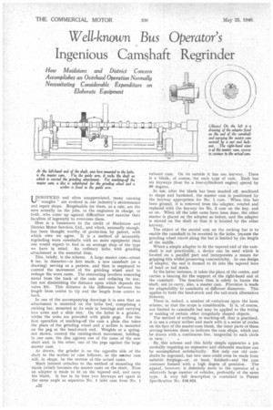
In one of the accompanying drawings it is seen that an attachment is mounted on the lathe bed, comprising a rocking bar, mounted at its ends in bearings and carrying two arms and a slide rest. On the latter is a grinder, whilst the arms are provided with guide pegs. For the flist operation of marking-off the cam a plain disc takes the place of the grinding wheel and a scriber is mounted on the peg at the head-stock end. Weights or a spring, not shown, control the nicking-shaft movement, holding, in one case, the disc against one of the cams of the new shaft and, in the other, one of the pegs against the large master cam.
As drawn, the grinder is on the ouposite side of the shaft to the scriber or cam follower, so the master cam will, in shape, be the reverse of the actual cams.
Much interest attaches to the method of mounting the blank (which becomes the master cam) on the shaft. First an adapter is made to fit on the tapered end, and carry the blank. It has in its bore two keyways set apart at the same angle as separates No. 1 inlet cam from No. 1 exhaust cam. On its outside it has one keyway. There is a blank, of course, for each type of cam. Each has six keyways (four for a four-cylindered engine) spaced by 60 degrees.
In use, after the blank has been marked off, machined to shape and hardened, the master cam is positioned by the keyway appropriate for No. 1 cam. When this has been ground, it is removed from the adapter, rotated and replaced with the keyway for No. 2 cam on the key, and so on. When all the inlet cams have been done, the other master is placed on the adapter as before, and the adapter is moved on the shaft so that it is located by the other keyway. '
The object of the second arm on the rocking bar is to enable the camshaft to be reversed in the lathe, because the grinding wheel travel along the bar is limited by the length of the saddle.
Where a simple adapter to fit the tapered end of the camshaft is not practicable, a device can be used which is located on a parallel part and incorporates a means for gripping this whilst preserving concentricity. In one design of adapter, the end is formed to fit into the tapered bore of head or tail stock.
Inthe latter instance, it takes the place of the centre, and carries a bearing for the support of the right-hand end of the camshaft. The function then is solely to locate the shaft, not to carry, also, a master cam. Provision is made for adaptability to camshafts of different diameters. This applies to both the head-stock and the tail-stock alternative fitments.
There is, indeed, a number of variations upon the basic scheme, so that the scope is considerable. It is, of course, not limited to camshafts but may be applied to the truing or making of certain other irregularly shaped objects.
' The method of scribing, in marking-off, that is practised. is to use a rotary scriber and mark with it a series of circles on the face of the master-cam blank, the inner Parts of these serving between them to indicate the cam shape, which can be drawn with a continuous line, tangential to each circle in turn.
By :this scheme and this fairly simple apparatus a job normally requiring an expensive and elaborate machine can be accomplished satisfactorily. Not only can old camshafts be reground, but new ones could even be made from suitable forgings—or, at least, finished—and the cam contours formed with a high degree of precision. The appeal, however, is definitely more to the operator of a relatively large number of vehicles, preferably of the same type. A very full description is contained in Patent Specification No. 518,923.