


Patents Completed.
Page 20
If you've noticed an error in this article please click here to report it so we can fix it.
notax Sell-starter. Saurer Detachable Wheel. Piston Construction.
An Improved Universal Coupling.
Copies of complete specifications of the patents published on this page can be obtained from the Sales Branch, Patent Office, Holborn, W.C., at the cost of sixpence for each specification.
E. AEON and E. Jinx, Na. 10,459, dated 19th July, 1915.— According to this invention the pinion on the shaft of the starting motor is free, but is connected to a disc fast on the shaft by ball-ended links. The pinion is free to slide endwise into one position in which it engages a toothed rim on the flywheel and a dog-clutch on the motorshaft, or into another position in which it is free from both. Normally, it is the free position, and in. this case the ball-ended links are inclined to the motor shaft.
When the motor is started, the disc is simultaneously moved but the pinion lags slightIV and the links are thereby straightened out slightly until the pinion engages with he flywheel. This engagement holds the pinion stationary so that further rotation of the disc causes the ball-ended links to be straightened out parallel with the motor shaft, thereby completely engaging the pinion with the flywheel and with the dog-clutch so that the drive is transmitted to the engine shaft.
As soon as the engine over-runs the starting motor, the pinion is turned more quickly' than the disc, and the ball. ended links are thereby tilted again, permitting the pinion to he moved to its inoperative position by a spring.
Anossss Samna, LTD., No. 4292, 1915; dated under International convention, 2nd March, 1914.—This specification describes a simple construction of detachable wheel of the type in which a driving shaft is mounted inside the rear axle, and the wheel turns freely on the rear axle. A castellated disc fixed on the end of the driving shaft engages recesses in the wheel-hub and it is screwed to the wheel-hub and to the collar on which the wheel is mounted. By undoing one set of screws, either the wheel ca,n be removed from the huh, or the driving shaft can be withdrawn, the other part semaiming fixed.
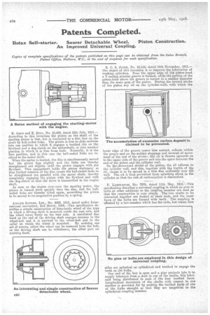
• R. C. S. JAMIE, N. 16,116, dated 16th November, 1915.— The object of this invention is to improve the lubrication of working cylinders. Near the upper edge of the piston-head a V-section annular groove is formed, while the portion of the piston-head above the groove is turned to, a smaller diameter than the main pars. of the piston. During the inward stroke of the piston any oil on the cylinder-walls with which the lower edge of the groove comes into contact, collects 'within the groove and on the =sudden stoppage and reversal of movement at' the end of the stroke ; this oil is thrown upwards on to the upper side of the groove and into the space between the end of the piston and the cylinder wall. On the downward stroke of the piston, the oil adheres to the cylinder wall, and this, together with the inertia of the oil, causes it o be spread in a thin film uniformly over the wall. The oil is thus prevented from splashing about in the cylinder so that the risk of carbonization is diminished.
F. Lassmotrau, No: 7078, dated 11th May, 1915.—This
specification describes a universal coupling in which no pins or bolts or other additions to the coupling member are used so that the construction is very simple. The two shafts to 'be connected tsSgether are forked at their ends, and the inner faces of the forks are formed with teeth. The coupling is effested by a box-member which has flat ends, but whose four
sides are spherical or cylindrical and toothed to engage the teeth on the forks.
One end of the box is open and a pipe projects into it to supply lubricant from a duct in one of the shafts, this lubricant being distributed to each of the four toothed• faces. Longitudinal movement of the shafts with respect to on another is provided for by making the toothed parts of one of the forks straight so that they are tangential to the cylindrical coupling member.