


Patents Completed.
Page 22
If you've noticed an error in this article please click here to report it so we can fix it.
Complete specifications of the following patents will be sent to any address in the United Kingdom upon receipt of eightpence per copy at the Sale Branch, Patent Office, Holborn, W.C.
AUTOMATIC LUBRICATOR.—Marti and Berna Commercial Motors, Ltd.—No. 21,487, dated 15th September, 1910.—In this specification there is described all automatic lubricator for explosion engines which is arranged to give a regular flow of lubricant to the bearings when the engine is running without the use of a special oil pump. The crankcase is divided into two portions by a web which carries one of the main bearings ; a flywheel and the head of the connecting rod revolve in one chamber, while in the other is arranged an oil-feed wheel. A lateral opening is provided in the plane of this wheel, from which the oil is carried through conduits to the bearings and thence to the crankpin ; suitable sightholes are provided to show if the flow of oil is continuing. A connection is made between the two portions of the crank chamber at the oil outlet, and this is arranged to drain the right-hand division of the crank chamber ; a non-return valve prevents the oil flowing into this cham ber, hut allows it to flow from thence into the chamber containing the oil-feed wheel. Owing to the pressure which occurs in the crank chamber proper at every second revolution of the engine, the oil cannot remain there, but it is driven out and returned to the other chamber, wherein is situated the lubricator wheel.
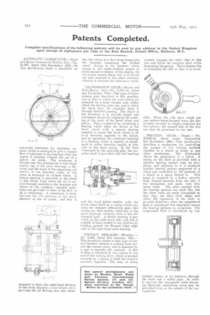
TRANSMISSION GEAR.—Royce and Rolls-Royce, Ltd.—No. 3,341/11, dated 2nd November, 1910.—The type of transmission gear described in this specification is that in which the road wheels are mounted on a fixed tubular axle within which the driving axles run, and in which the drive from the propeller shaft is through bevelled gearing. The object of the invention is to provide simple and convenient means for adjusting the meshing of the teeth of the bevel wheel and pinion. This is achieved by combining a bearing which takes the thrust of the bevel wheel with a second bearing adapted to retain the bevel wheel in an axial direction opposite to the thrust, and by mounting the combined bearings in a housing which is capable of adjustment in either direction axially in relation to the fixed casing. In the form illustrated by the sectional plan, the propeller shaft is provided with ball bearings
and the bevel pinion meshes with the bevel wheel fixed on a casing which contains the ordinary differential gear ; this casing can slide axially, relatively to the main bearing, carrying with it the differential gear. A Artist bearing is provided on the right-hand side, and this is capable of being locked in any position by bedding against the flanged collar adjacent to the right-hand main bearing.
CONTACT BREAKER.—Fletcher. — No 2,435, dated 31st, January, 191L— This invention relates to that type of contact breaker wherein a rocking lever carries the contact piece, and is operated by a cam to separate the contacts. A disc of fibre is attached by two screws to one end of the rocking lever, which is pressed upwards by a spring to hold the contacts normally together. The cam, on being rotated, engages the other edge of this disc and forces the contacts apart while depressing the spring. The invention lies in arranging the disc so that it is rever sible. When the side upon which the cam surface bears becomes worn, the disc is easily reversed by simply removing the two screws; the unused side of the disc can then be presented to the cam.
FRICTION GEAR. — Diesel. — No. 23,844.10, dated under Convention 3rd November, 1909.—This specification describes a mechanism for controlling the contact of two friction surfaces whether in a clutch or brake or any other mechanism. The illustration shows the application to a clutch. A casing on the shaft is provided with a suitable bearing surface near its periphery, and adjacent to it is arranged another bearing surface supported on a wheel and controlled by the pressure of a liquid in a space behind it. This space is occupied by a hollow annular body formed separate from the rest of the mechanism and made with thin metal walls. The sides parallel with the bearing surfaces are made flat, but the other walls are made corrugated so that they can alter their shape and allow the expansion of the body in an axial direction ; when the compressed fluid is introduced this expansion causes the bearing surfaces to co-operate. The compressed fluid is introduced by any suitable means, as for instance, through the shaft and a radial pipe. In order to prevent the corrugated walls becoming flattened, reinforcing wires may be provided lying on the outside of the corrugations.