


The Straker-Squire Motor Omnibus.
Page 8
Page 9
If you've noticed an error in this article please click here to report it so we can fix it.
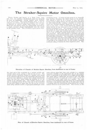
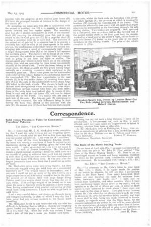
Messrs. Straker and Squire, of 9, Bush Lane, London, F..C., are making a double-deck petrol bus designed to carry 34 passengers, having several novel features in its construction. The engine develops 2 4h . p. at 950 revolutions per minute, and has four cylinders, each io5
in diameter by i3omm. stroke, these being cast in pairs. Both inlet and exhaust valves arc mechanically operated by a single camshaft placed longitudinally over the centre of the cylinder heads. This camshaft is gear driven from
the front end of the crankshaft by a vertical spindle and suitable spiral gears, giving a ratio of two to one. The spindle carries a governor acting on a throttle valve placed in the induction pipe between the carburetter and inlets ; this governor also operates a second valve placed immediately below the first one, which varies the quantity of air admitted to the induction pipe. Low tension magneto ignition is employed, driven off the front end of the crankshaft by two gear wheels of equal size, the one on the armature shaft being utilised to drive a high-speed centrifugal water circulating pump. A feature of this pump is an unusually long bearing, extending the whole length of the spindle. The radiator is built up of a number of thin, flat tubes having a large cooling surface; the top and bottom chambers are split longitudinally, making it possible to remove the halves for cleaning purposes should the necessity for this arise at any lime. A fan placed behind the radiator and bolted directly to the front end of the crankshaft ensures efficient circulation of air. The carburetter is of the jet type and placed on the left-hand side of the engine; the outer end of the air supply pipe encircles the exhaust chamber, to allow of the air being warmed before finding its way into the carburetter. The crank chamber is provided with three long bearings, lined with anti-friction metal, to accommodate the nickel steel crankshaft. The connecting reds are hollow, being made solid and afterwards drilled, and have scoops at their lower end, which dip into the lubricating oil, lifting it upwards to the gudgeon pins ; by this means a constant automatic oiling is insured for these important parts. Sep arate exhaust pipes lead from each cylinder to a common expansion chamber at the right-hand side of the engine, which is connected to the silencer by a single exhaust pipe. The petrol tank is underneath the driver's seat and holds zo gallons of spirit, or ample for a day's work, as the bus is estimated to run eight miles on a gallon. The male portion of the leather-lined conical clutch (A) is permanently attached to the primary shaft (B) in the first gear box by a coupling joint (C), declutching being effected by a longitudinal movement of the entire shaft. This feature, in con junction with the adoption of two distinct gear boxes (D) (E) form the principal features of interest in the design of the chassis (12). By operating the usual gear box (D) in conjunction will the second or auxiliary one (E) it is possible to obtain six speeds forward and two reverse speeds. The secondary gear box (E) is placed immediately in front of the countershaft (H) carrying the differential gear (G), and is connected to the forward gear box (D) by a propeller shaft (I) having a universal joint (J) at each end. The function of the second set of gearing in a separate box is to provide a retatively low ratio for each of the three speeds in the ordinary box, the combination of the other ratio in the second box bringing into action a speed of comparatively high value ; a single change-speed lever (K) at the driver's left operates the auxiliary gears. This feature will be found of use when, for example, the vehicle is running light from any reason, such as going to and from the depot or stables. The change-speed gear wheels in both boxes are of the ordinary sliding type, and are controlled by three levers conveniently situated at the driver's left. Two of the levers belong to the usual gears, the third actuates the two gears sliding longitudinally on a revolving transverse shaft contained in the secondary gear box. These latter gears can he intermeshed with either of two wheels bolted to the differential drum on the countershaft (H). The final transmission to the road wheels (L) is by two roller chains (M) running from sprockets (N) on the ends of the countershaft to two chain rings (0) bolted to the back wheels. The chassis is built up of channel steel strengthened where necessary by cross stays. Semi-elliptical springs support both front and back axles; those of the latter have longitudinal play, by means of pins fitted in each end of the top leaves (P), and run in slotted brackets (R) on the frame. Two radius rods are used on each side of the axle. The forward pair (S) correspond to those usually employed, the only difference being in their having the back ends slotted at the junction with the axle (T); the second pair (U) have their forward ends coupled
to the axle, whilst the back ends are furnished with power. ful volute springs (V), the pressure of which is received by brackets (W) towards the rearward end of the frame. This combination effectually does away with all shock that might otherwise be transmitted to the machinery through the side driving chains. Two brakes are employed. One, operated by a foot-pedal, acts on a drum (X) on the forward end of the second motion shaft in the front gear box; the second, worked by a hand lever at the driver's right, causes bands to grip two drums (Y) bolted to the inner side of the chain sprockets on the driving wheels. The price of the vehicle complete is c,ftso.