


QUIET GEAR-CHANGING BY PRESSING A BUTTON.
Page 9
Page 10
Page 11
If you've noticed an error in this article please click here to report it so we can fix it.
An Ingenious Servo Motor Which Obviates Manual Operation of Gear Lever and Clutch.
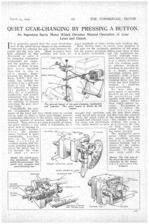
T is generally agreed that the most out-of-date • part of the petrol-driven chassis is the mechanism employed for altering the gear ratio between the • engine and the back axle. Many inventors have been attracted by this problem, and have en deavoured to solve it by designing alternative mechanisms for replacing the gearbox, and a number of these devices have been described from time to time in this journal. MajorGeneral Sir Richard M. Ruck, K.B.E., .RE. (retired), has tackled the problem from a different point of view. He does not endeavour to replace t h e gearbox — Which, after all, is a perfectly satisfactory and reliable component—but inns at relieving the driver from the necessity of directly operating the gear lever and clutch.
Undoubtedly, the careful. co-ordinated movements of the hand and foot, which must be carried out in circler to effect a quiet gear-change, present considerable difficulties to the novice, and require an immense amount of practice before proficiency is obtained. Many drivers are quite incapable of changing gears quietly, a faet which is responsible for a great deal of damage to , the gear teeth. Furtherin o r C, the physical labour involved is quite Considerable, p a r ticularlv in the case of buses working in crowded streets with frequent stopping places, on which the driver has to run through the range of three or more gears hundreds of times during each working day.
Many devices have, of course; been designed in the past for the automatic operation of the gears, but the present invention differs from 'these in that it is purely mechanical, and the mechanism em ployed, although somewhat difficult to describe, is of a simple character, with few working parts. In addition, double-declutching is provided for in asimple manner, operating entirely automatically both when changing up and when changing down, and this
ction has been found to Produce a markedly quiet gear-change.
We have seen the servo motor in operation fitted to an old car, and the precision and rapidity with which gearchanges were effected were really almost un
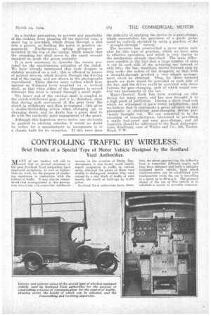
canny. By pressing or pulling a button the servo d e v. i c e was brought into operation, and the gear lever obediently moved into neutral and then into the required notch, the clutch pedal in the murntime being depressed and released twice. The rapidity of changing down was particularly striking, this being a very useful feature on hil s, as it prevents the vehicle from losing much speed while the gears are being changed.
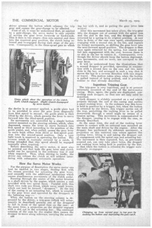
LevER The mechanical servo motor, which performs the operations is contained in a simple and compact housing, and is driven by the engine. Although running continuously, it do,ee no real work until the driver presses the button which releases be trip gear and causes the gear-change to be effected. First of all, it must be understood that, as applied to a gate-change, the servo motor is only capable of moving the gear lever forwards or backwards. _ This it does in two stages—first into neutral and then into the required gear position, the clutch being released and re-engaged during each stage of the process. Consequently, in the three-speed gate to which the device is at present applied, a guide plate had to be provided to steer the gear lever diagonally from first speed to second; the guide plate is then lifted by the driver, which permits the lever to move forward into the third-speed position. Its movements are controlled by a simple button control mounted on the steering column, which, when depressed, causes the lever to move forward into first speed or third (according to the position of the guide plate), and, when pulled, causes the gear lever to move back either from third or first-speed position into the second-speed position. Only a very light touch is required in operating the button. The reverse notch is normally covered by a catch, it being intended that this speed should be engaged manually when requireti.. • Before describing the servo motor, it must also be pointed out that both the gear lever and clutch pedal can be operated in the ordinary way if and when required. Thus, when driving in traffic, the driver can release the clutch at will without interfering with subsequent automatic operation.
How the Servo Motor Works.
For the purpose of description the servo motor can best be tackled in two stages, dealing first with the means provided for actuating the gear lever, and secondly with the additional mechanism which causes simultaneous movements of the clutch pedal. Running through the centre of tilt motor housing is a shaft driven by the engine, which carries a cam provided with two spiral faces. Parallel with this shaft two rods are fitted, which carry small levers, which can best be termed " droppers. ' At the top of the casing is an actuating bar, which is coupled to the gear lever and operated by the droppers in the following way:— When the button on the steering column is depressed by the driver, a trip-gear (which will subsequently be described) permits one of the droppers to fall in front of the spiral face on the cam ; at the same time, a projection on the dropper engages with a slot cut in the actuating bar. The continoal rotation of the cam by the engine then causes the dropper to move along sideways, carrying the actuat
B26
ing bar with it, and so pulling the gear lever into neutral.
After this movement has taken place, the trip-gear lifts the dropper out of contact with the spiral cam and the slot in the bar, and the dropper is then returned by a spring, to its original position. It, now falls in front of the cam once again, simultaneously engaging with a second slot in the bar, and repeats its former movements so shifting the gear lever into the next forward speed position. The dropper is then once again returned by the spring, but cannot now fail into engagement with the cam, because there is no slot in the bar to receive it. Consequently, even though the driver should keep the button depressed, two movements, and no more, are conveyed to the gear lever. It will be understood from the illustrations that a second dropper is provided, operating in conjunction with a second face on the cam and two more slots in the bar, and arranged in such a way that it moves the bar in a reverse direction with two stages of travel. This motion takes place when the button is pulled instead of being pushed, and is precisely similar to that already described.
Ingenious Tripping Gear.
The trip-gear is very ingenious, and is at present externally mounted at the end of the servo-motor casing. Here, again, the parts are duplicated, controlling each dropper, so that one set only need be described.
Each dropper is slidably mounted on a rod which projects through the end of the casing and carries a small rocking lever. In the Ordinary way this lever is held in position by a trigger, but, :when the button is actuated by the driver, this trigger moves out of the way, permitting the rocking lever to be pulled downwards through a small anule by means of a tension spring. This movement is communicated to the dropper, causing it to engage with the cam, as already described.
At the same time, the end of the rocking lever comes in contact with an external cam mounted on the main shaft and driven by the engine. After the dropper has performed its sideways movement, a projection on this external cam comes against the rocking lever, lifting it and taking the dropper out of engagement with the spiral cam and actuating bar. The movement is then repeated, but, as previously pointed out, can only take place twice, the dropper and rocking lever being held in position by the bar, so that when the button is released the trigger auto matically re-engages. As a further precaution, to prevent anY possibility of the rocking lever jumping off the external cam, a small lug is provided, which drops through a slot into a groove, so holding the parts in positive engagement. .Furthermore, spring plungers are mounted at the top of the casing, which ensure that the actuating bar shall move by the exact 'amount required to mesh the gears correctly.
It iS now necessary to describe the means provided for the simultaneous actuation of the clutch. We have already mentioned that each dropper is slidably mounted on a rod; this is effected by means of splined sleeves, which Project through the driving end of the casing,. and are shown in the photographs reproduced. These sleeves carry collars which bear aginst an S-shaped lever mounted on a vertical shaft, so that when either of the droppers is moved sideways this lever is turned through a small angle.
The lower end of the vertical shaft is coupled to the clutch-withdrawal gear, and it is, therefore, clear that during each movement of the gear lever the clutch is withdrawn and then re-engaged : this gives a double:declutching action when changing up or changing down, and no doubt has a great deal to do with the markedly quiet engagement of the gears.
Although this ingenious servo motor can obviously he applied to existing vehicles, it would no doubt be better for a manufacturer to incorporate it in a chassis built for its reception. If this were done the difficulty 'of applying the device to a gate-change, which necessitaIes the provision of a guide plate, could be entirely obviated by using a gearbox of the " straight-through " variety. The inventor has constructed a servo motor suitable for this type of gearbox_, which we have seen in effective operation, and which is very similar to the mechanism already described. The Main difference consists in the fact that a large number cif slots is cut in each side of the actuating bar: instead of only two ; the bar, therefore, moves forward step by step under the action of the droppers, so that with a straight-through gearbox a very simple arrangement could be obtained. Thus, for three forward speeds six slots would be provided at each .side of the bar, and the driver could be provided with three, buttons for gear-changing, each of which would control two movements of the bar. • . , • Major-General Ruck has been working ,on this device for many years, and has now brought it to a high pitch of perfection. During a short road test which we witnessed it gave every satisfaction,. and we believe that it represents a great advance on any, pneumatic or electrical gear-changing device previously brought out.. We can commend it to the attention of manufacturers interested in providing a really fool-proof and easy gear-change,, and all inquiries should he addressed to the Mack Automatic Gear Syndicate, care of Wailes and Co., 386, Liston Road, N.W.