


REMEDYING TRANSMISSION TROUBLES.
Page 29
If you've noticed an error in this article please click here to report it so we can fix it.
Driver's Experiences with Universal Joints, Taper Shafts and the Lubrication of Chains_
UNIVERSAL joints have given trouble to two of our readersrecently, and both of them exercised Considerable ingenuity in getting out, of
their difficulties. Of the two letters which have reached us on this matter.. the better one is, we think, that from " W.F.," of Alloa; at any rate, his solution is more widely applicable, and we therefOre award him the 15s. prize. Be commences his letter by a general complaint anent the liability of parallel splined shafts to work loose in the parts which are fitted upon them, Further, he remarks, once wear has developed, there is no means of circumventing it or of tightening the loose part upon its shaft. If the shaft be taper, then conditions are altogether different.
It is sometimes possible to tighten a part upon a parallel splined shaft by driving pieces of short steel along the splines, but, in the majority of eases, the, effect is to throw the part out of centre with the shaft-, causing uneven running, with its attendant lack of balance and other evils.
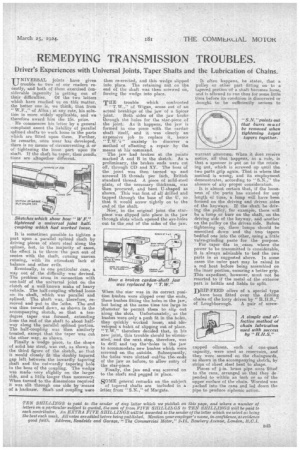
Eventually, in one particular case, a way out Of the difficulty was devised. The problem arose in connection with one-half of the universal joint on the clutch of a well-known make of heavy vehicle. The half-coupling wsorked loose on its shaft, which was parallel and splined. The shaft was, therefore, removed and put in the lathe. The end was then turned down, as shown in the accompanying sketch, so that a tendegree taper was formed, extending from the end of the shaft to about halfway along the parallel splined. portion. The half-coupling was then similarly treated, except that the taper was cut the other way, as shown.
Finally a wedge piece, to the shape of solid bar steel, was cut, as shown in the third figure of the sketch, so that it would closely fit the doubly tapered gap left between the inwardly tapering shaft and the outwardly tapering hole in the boss of the coupling. The wedge was made very slightly on the larger side, and a little longer than necessary... When turned to the dimensions required it was slit through one side by 'means of a hacksaw. Shaft and coupling were
then re-erected, and this wedge slipped' into place. The retaining nut on the end of the shaft was then screwed on, forcing the wedge into place.
THE trouble which . confronted " T.W. " of Wigan, arose out of an actual breakage of the jaw of a Spicer
joint. Both sides of the jaw broke through the holes for the star-piece of the joint. As it happens, the jaw is formed in one piece with the card an shaft itself, and it, was clearly an expensive job to replace it, hence " T.W.'s " anxiety to discover a method of effecting a repair by the means at his command.
The jaw had broken at the points marked A and B in the sketch. As a preliminary, the broken ends were cutoff, through OD and XY. The boss of the joint. was then turned up and screwed 16 threads per inch, British standard thread. A piece of mild-steel plate, of the necessary thickness, was then procured, and bent U-shaped as shown. This was first of all drilled and tapped through the base of the V, so that it would screw tightly on to the end of the shaft.
Now, in the original joint the starpiece was slipped into place in the jaw through slots which opened the eye-holes out to the end of the sides of the jaw.
When the star was in its correct position bushes were slipped over the ends, these bushes fitting the holes in the jaw, but being at the same time too large in ;diameter to permit them to slip out along the slots. Unfortunately, as the bushes were only a push fit in the holes, they quickly worked loose, and tde. veloped a habit of slipping out of place. i " T.W." therefore decided that, n his new joint, this trouble should be eliminated, and the next step, therefore, was to drill and tap thesholes in the jaw to accommodate new bushes which were screwed on the outside. Subsequently, the holes were slotted outc-to the. ends of the jaw as before, to allow entry of the star-piece. Finally, the jaw end was screwed on to the shaft and pegged in place.
SOME general remarks on the subject of tapered shafts are included in a letter from " S.N.," of Margate. It often happens, he states, that a pulley or other part fitting on to a tapered portion of a shaft becomes lease, and is allowed to run thus for some little time before its condition is discovered or shought to be sufficiently serious to warrant attention. When it does receive notice, all that happens, as a rule, is that a spanner is put on to the retaining nut, which is screwed up until the two parts grip again. That is where the method is wrong, and its employment demonstrates, according to " S.N., ' the absence of any proper consideration.
It is almost certain that, if the looseness of the parts has existed for any length of time, a lump will have been formed on the driving and driven sides of the keyways. If the shaft be driving the pulley, for example there will be a lump or burr on the shaft, on the driving side of the keyway, and another on the pulley on the driven side. Before tightening up, these lumps should he smoothed down and the two tapers bedded one into the other, using a little valve-grinding paste for the purpose.
For taper -fits in, .cases where the power to be transmitted is considerable, it is always advisable to bed the two parts in as suggested above. In some cases the outer part may be raised to a red heat before being assembled on the inner portion, ensuring a better grip. This expedient, however, must .not be resorted to if the metal of the exterior part is brittle and liable to split.
DRIP-FEED oilers of a special type have been fitted over the driving chains of the lorry driven by "11.11.S.,'
of Loughborough. A pair of screw capped oilcans, each of one-quart capacity, were used as reservoirs, and they were secured on the rhainguards, as shown in the accompanying sketch, by strips of sheet steel bent to shape. Pieces of i-in. brass pipe were fitted to the cans, arranged so that they depended to within an inch or so of the. upper surface of the chain. Worsted was packed into the cans and led down the pipe to produce siplionic action.