


"Impulse Starter" for Oil Engines
Page 34
If you've noticed an error in this article please click here to report it so we can fix it.
WHEN an oil engine is WV being .started, especially by an electric starting-motor, the rotational speed is' very low and often is insufficient to ensure an adequate fuel delivery from the injection pump. To deliver a certain charge, in these circumstances, is the
object of a fuel accumu lator shown in patent No. 552,725, by Joseph Lucas, Ltd., R. J. Ifield and E. A. Watson, all of Great King Street, Birmingham, 19. Actually, the device is, to the injection pump, what the impulse-starter is to the magneto.
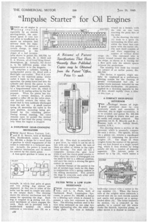
It comprises a cylinder, housing a spring-loaded piston (1), fitted with a fluid-tight cup-washer. Port 6 is connected to the injection pump, whilst outlet 4 leads to the injectors. In operation, the pump forces fuel into the cylinder and moves the piston to the right, the exit being closed, meanwhile, by a long-stemmed valve (5), which is assisted in its sealing action by the fuel
pressure. When the piston has travelled a certain distance, it abuts against a collar (2) on the valve stem, and forcibly unseats the valve; the stored fuel is then suddenly discharged from the exit (4). • A small tension spring (3) maintains the valve in the open position, re-seating being performed by the returning piston: During normal running, the valve remains open to permit the normal passage of fuel from the pump, closing only when the engine is stopped.
A FOOLPROOF GEAR-CHANGING MECHANISM
.FROM David Brown Tractors, Ltd., and H. E. Merritt, both of Meltham Mills, Huddersfield, comes, in patent No. 552,564, a design for a novel form of gearbox in which engagement of the ratios is controlled in a foolproof manner. Actually, the patent is based on the selector mechanism and its means for control by the clutch pedal.
A. four-speed gearbox is taken as an
example, in which four pairs of gears and two sliding dog sleeves are employed, so that one or other of the latter can be used to couple any, ratio to the output shaft. Thedrawing shows the selector mechanism and the means for operating the dogs. Each dog is coupled' to.. sliding rod (1), axial movement of which engages the teeth. Each rod is provided with a double-hook member (2) which embraces a two-lobed cam (9) on a shaft (4). This shaft is controlled by a gear lever, by which it can be set in line with any single hook; the ears of these are offset as shown in the righthand drawing. The shaft (4) has a composite motion—the gear lever slides it and the clutch pedal rotates it. Only when the clutch is disengaged can the shaft be slid to a different position, and once the clutch is driving the gears cannot be moved.
A further feature of the patent is the use of ratchet-type teeth on the dogs, in conjunction with a spring cushion in the sliding mechanism. This permits the dogs to over-ride each other until their speeds synchronize.
FILTER WITH A LOW FLOWRESISTANCE FROM Automotive Products Co., Ltd., and L. A. Poole, both of Tachbrook Road, Leamington • Spa. comes, in patent No. 552,082, a design for a filtering unit which is claimed to possess a verylow resistance to fluid flow. The filtering medium used is flat wire strip embossed on one edge into slight upstanding ribs, the other edge being plain. The wire is helically
wound on a former, with the rib on one turn touching the plain face of the next.
Iii the drawing, the inlet (1) leads to. a space (2) surrounding the filter unit, whilst the inner face connects with the outlet (5). The unit itself consists of end discs supporting a number of vertical metal strips (3). The embossed wire is closely wound around the outside of the strips, as shown at 4, leaving for a flow path only the minute spaces between the projections.
The winding wire itself has formed the subject of an earlier patent, No. 385,755.
This device, it appears, might useluny be employed as a preliminary filtering system for the cleaning of grossly contaminated fuel oils, or similar waste material, intended for use as fuel after clarification. Air pressure, applied in a direction opposite to the oil flow, should rapidly clean a filter of this type.
A COMPACT HIGH-SPEED GOVERNOR
THE centrifugal masses of high
1 speed governors must be very accurately made, and assembled if vibration, due to slight eccentricity, is to be avoided, and patent No. 552,320 shows a design in which this end can be easily and simply achieved The patentees are H. R, Ricardo and R. J. ebusins, both of 21, Suffolk Street, London. S.W.1.
The drawing shows a section of the governor, which is unusually compact for such a device. The spindle, driven via a pinion (4), rotates a cup-shaped member (1) containing the governor weights (7). The shape of these weights forms the essence of the patent; they are first formed as a single turned • ring, which is then divided by being axially slit into a number of separate segments. The fulcrum point is formed by a lip (2), which makes a knife-edge contact with a corner in the cup member (I). When the heavy tails of the weights move outwards a curved end (3) .on each travels axially and exerts end pressure on a springloaded slider (5). The latter transmits its motion, via a cross-slot in the spindle, to a central rod (6) which works the throttle, injection pump, or other device it is desired to control.