


ew Screw-operated Refuse Body
Page 62
If you've noticed an error in this article please click here to report it so we can fix it.
T"problem of dustless refuse collection is now being tackled with earnestness, and patent No. 466,104 shows the latest move in this direction. The inventor is G. L. Fisher, 561, Old Kent Road, London, S.E.1.
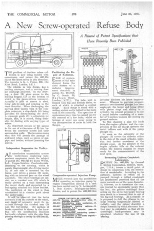
The vehicle, in this design, bas a loading conveyor, and a moving floor for discharge purposes. In the drawing, a door (2) gives access to the loading hopper (1) at the bottom of which is the power-driven conveyor. Actually a pair of screws is used, lying side-by-side and rotating in the same direction. When discharging, the moving floor carries with it the complete conveyor, a dog-clutch (4) being provided for disconnecting the drive. A, telescopic guide (2) is adjustable for length, this, it is stated, being desirable for dealing with varying types of refuse.
An important feature of the patent is the use of a:clearance of 2i ins, between the conveyor screws and their surrounding walls. The inventor states that this will permit the passage of awkward refuse, such as pieces of gaspipe and bottles, without jamming the screws.
Independent Suspension for Trolley.
buses.
AN unorthodox transmission system for trolleybuses employing independent suspension forms the subject of patent No. 465,725 by Tatra Works, Ltd., Prague-Smichov, Czechoslovakia. Referring to the drawing, which is purely diagramnigic, the driving motor (1) of one side is mounted on the frame, and drives a pinion (2) meshing with an internal gear on the wheel assembly. The wheel bearings are carried on a cranked arm (3) which is freely pivoted on a tube surrounding the motor shaft, and supported by a leaf-spring attached to a frame bracket. The oscillation of the wheel is thus constrained to a circular path about thb motor axis.
It will be observed that the brake assembly is on the outside of the wheel, and. must of necessity exert its reactions through the cranked arm (3) and the leaf-spring. No method of brake operation is shown in the drawing, but the specification mentions hydraulic cylinders, with the pipe lines passing through a cavity in the arm (8).
is4S Facilitating the Repair of Radiators.
EASE of replacement of the tube element forms the chief feature of a radiator improvement described in patent No. 464,918, by C. Searle, 53, B a y h am Street,
London, N.W.1. The tube _unit is formed with top and bottom tanks, to each of which is attached a central flange. Each flange is fitted with a sealing washer and is bolted to the main tank of the assembly. The operation of replacement may thus be carried out by the removal of a few bolts, Whilst no leakage of water can occur owing to the incorporation of cocks in both the flanges.
Compression-operated Injection Pump.
NAUCH research into the possibilities iViof operating an injection pump by engine compression instead of a cam has been carried out by V. Archaouloff, 1, Rue Carnot, Boulogne-sur-Seine, France, and in patent No. 465,236 this inventor discloses his latest improvement. Whereas in previous arrangements a two-diameter plunger has been employed, the larger end being fitted with piston rings and sliding in a cylinder, the present proposal is to use a metal bellows consisting of a number of V-section washers (2) mating on ground surfaces.
To this chamber a pipe (3) leads• from the engine cylinder, and the compression of the air charge operates the metal bellows and with it the pump plunger (I).
So soon as the extremity of the plunger (1) covers the delivery orifice in the side of the small cylinder, injection and further movement of the Plunger cease. As the pressure in the engine cylinder falls on the exhaust stroke, the bellows resumes its shape ready for the commencement of the next cycle.
Promoting Uniform Crankshaft Lubrication.
PATENT No. 465,580, by General Motors Corporation, Detroit, Michigan, U.S.A., covers a detail point of design in connection with the lubrication of crankshafts, According to the patentee, Systems in which oil is pumped through a drilled crankshaft are satisfactory provided that all the main journals are of the same diameter. If, however, as is sometimes the case, one journal be appreciably larger than•the rest, the greater centifugal force acting on the oil in this larger bearing may result in a lessened flow to one of the big-end bearings. As remedy, it is proposed to drill the Mlways in the large bearing tangentially instead of .radially, and the patent describes a simple formula by which the exact location may be calculated, so that all the centrifugal back-pressures may be equalized, whatever the size of the bearing.