


Air-Pressure Brake Return
Page 74
If you've noticed an error in this article please click here to report it so we can fix it.
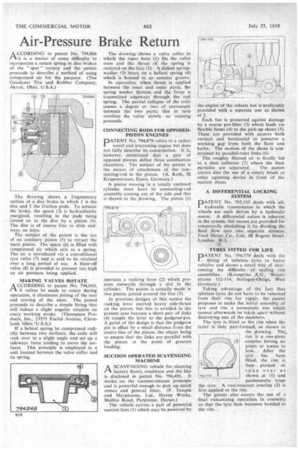
ACCORDING to patent No. 794,866 it is a matter of some difficulty to incorporate a return spring in disc brakes of the " spot" variety and the patent proceeds to describe a method of using compressed air for the purpose. (The Goodyear Tire and Rubber Company, Akron, Ohio, U.S.A.)
The drawing shows a fragmentary section of a disc brake in which I is the disc and 2 the friction pads. To actuate the brake, the space (3) is hydraulically energized, resulting in the pads being forced on to the disc by a piston (4). The disc is of course free to slide endways on keys.
The subject of the patent is the use of an auxiliary piston (5) to retract the main piston. The space (6) is filled with compressed air which acts as a spring. The air is introduced via a convefitional tyre valve (7) and is said to be retained over a long period of use. A blow-off valve (8) is provided to prevent too high an air pressure being applied.
MAKING VALVES ROTATE A CCORDING to patent No. 794,049, g"i if valves be made to rotate during operation, it eliminates pitting of the seat and scoring of the stem. The patent proceeds to describe a simple fitting that will induce a slight angular rotation on every working stroke. (Thompson Products, Inc., 23555 Euclid Avenue, Cleveland, Ohio,'U.S.A.)
If a helical spring be compressed radially between two surfaces, the coils will rock over to a slight angle and set up a sideways force tending to move the surfaces. This principle is employed in a unit located between the valve collar and its spring. The drawing shows a valve collar in which the taper bore (1) fits the valve stem and the thrust of the spring is received on the face (2). A dished springwasher (3) bears on a helical spring (4) which is housed in an annular groove.
In operation, when thrust is applied between the inner and outer parts, the spring washer flattens and the force is transmitted edgeways through the coil spring. The partial collapse of the coils causes a degree or two of movement between the two parts; this in turn revolves the valve slowly as running proceeds.
CONNECTING RODS FOR OPPOSEDPISTON ENGINES DATENT No. 794,879 refers to a rather novel and interesting engine but does not fully describe its construction. It is, however, mentioned that a pair of opposed pistons define three combustion chambers. The subject of the patent is the means of attachment or the connecting-rod to the piston. (A. Roth, 58 Kaupenstrasse, Essen, Germany.)
A piston moving in a totally enclosed cylinder must have its connecting-rod assembly coming out of the side and this is shown in the drawing. The piston (I) operates a rocking lever (2) which projects outwards through a slot in the cylinder. The piston is actually made in two pieces, joined around the line (3).
In previous designs of this nature the rocking lever exerted heavy side-thrust on the piston, but this is avoided in the present case because a short pair of links (4) couple the lever to the gudgeon-pin. A point of the design is that the gudgeon pin is offset by a small distance from the centre-line of the piston, the object being to ensure that the links are parallel with the piston at the point of greatest loading.
SUCTION OPERATED SCAVENGING MACHINE
ASCAVENGING vehicle for cleaning factory floors, roadways and the like is disclosed in patent No. 794,491. It works on the vacuum-cleaner principle and is powerful enough to pick up small stones and general litter. (P. Temple and Marplesons. Ltd., Haven Works, Shillito Road, Parkstonc. Dorset.) The vehicle carries a pair of powerful suction fans (1) which may be powered by
he engine of the vehicle but is preferably provided With a separate one as shown at 2.
Each fan is protected against damage by a coarse pre-filter (3) which leads via flexible hoses (4) to the pick-up shoes (5). These are provided with castors both vertical and horizontal to preserve a working gap from both the floor and kerbs. The motion of the shoes is constrained by parallel-ruler links (6).
The roughly filtered air is finally led to a dust collector (7) where the finer particles are separated. The patent covers also the use of a rotary brush or other agitating device in front of the suction shoes.
A DIFFERENTIAL LOCKING SYSTEM
pATENT No. 795,535 deals with all-hydraulic transmission in which the wheels are each driven by a hydraulic .motor. , A differential action is inherent in the system, but means are provided for temporarily abolishing it by dividing the fluid flow into two. separate streams. Ford Motor. Co., Ltd., 88 Regent Street. London, W.1. . - 4 •
TYRES FITTED FOR LIFE
11DATENT No. 794,779 deals with the
fitting of tubeless tyies to, heavy vehicles and shows a novel Way of overcoming the difficulty • of • sealing rim assemblies. (Kronprinz KG.. Weyerstrasse 112-114, Solingen-Ohligs, West Germany.) Taking advantage of the fact 'that tubeless tyres do not have to be removed from their rim for repair, the patent proposes to make the initial assembly of tyre and rim a permanent one which cannot afterwards be taken apart without destroying one of the members.
The tyre is .fitted to the rim when the latter is only part-formed, as shown in the drawing. Thee rim is a one-piece ,annulus having no joints or seams to leak. After the tyre has been fitted, the rim is then pressed or ;pun over as :70. 47.79 shown at (1) and permanently traps the tyre. A rust-resistant 'coating (2) is first applied to the rim.
The patent also covers the use of a final vulcanizing operation in assembly so that the -tyre then becomes bonded to the rim.