


Gas Turbine for Road Vehicle
Page 58
If you've noticed an error in this article please click here to report it so we can fix it.
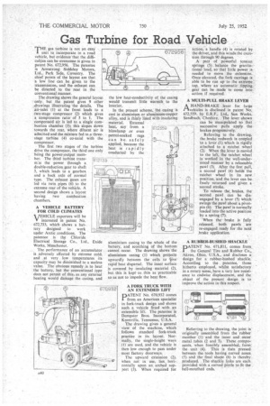
THE gas turbine is not an easy 1 unit to incorporate in a road vehicle, but evidence that the difficulties can be overcome is given in patent No. 672,956. The patentee is Armstrong Siddeley Motors, Ltd., Park Side, Coventry. The chief points of the layout are that a law line can be given to the transmission, and the exhaust can be directed to the rear in the conventional manner.
. The drawing shows the general layout -only. but the patent gives 9 other .drawings illustrating the details. The air-inteti (1) at the front leads to a two-stage compressor (2) which gives a compression ratio of 5 to 1. The compressed air is led to a single combustion chamber (3); this slopes down • towards the rear, where diluent air is admitted-and the mixture fed to a threestage turbine (4) co-axial with the compressor.
The first two stages of the turbine drive the compressor, the third one only being the power-output member. The third turbine transm:ts the power through a double-reduction gear to shaft 5, which leads to a gearbox and a back axle of normal type. The exhaust gases are led via twin pipes (6) to the extreme rear of the vehicle. A second design shows a layout having two combustion chambers.
A VEHICLE BATTERY FOR COLD CLIMATES
• VEHICLE exporters will be
interested in patent No 672,733, which shows a bat tery designed to work upder Arctic conditions. The patentee is the Chloride Electrical Storage Co., Ltd., Works, Manchester.
The performance of an accumulator is adversely affected by extreme cold. and ,at very, low temperatures its capacity may be diminished to a useless value. The obvious remedy is to heat the battery, but the conventional type does not permit of this, as any external beating would damage the casing. and Exide the low heat-conductivity of the casing would transmit little warmth to the interior.
In the present scheme, the casing is cast in aluminium or aluminium-copper alloy, and is thinly lined with insulating material. External heat, say from a blowlamp or even petrol-soaked rags can be safely applied, because the heat is rapidly conducted by the
aluminium casing to the whole of the battery, and scorching of the bottom cannot occur. The drawing shows the aluminium casing (1) which projects upwardly between the cells to tiverapid heat dispersal. The inner surface is covered by insulating material (2), but this is keptas thin as practicable so as not to impede the heat flow.
A FORK TRUCK WITH AN EXTENDED LIFT PATENT No. 670,932 comes from an American specialist in fork-truck design and shows such a vehicle fitted with an extensible lift. The patentee is Dempster Bros. Incorporated, Knoxville, Tennessee, U.S.A.
The drawing gives a general view of the machine, which follows standard fork-truck practice in its layout. Normally, the single-height ways (1) are used, and the vehicle is then low enough to pass under most factory doorways.
The upward extension (2), When not in use, lies horizontally upon an. arched support (3). When required for
action, a handle (4) is rotated 17137 672.96 the-driver, and this winds the exen
sion through 90 degrees.
A pair of powerful tension , springs (5). balance the gravita-.tional load, so that little power is. needed to move the extension. Once elevated, the fork carriage is able to be run up to the extreme • top, where an automatic .tipping gear can be made to come into action if required.
A MULTI-PULL BRAKE LEVER
AHAND-BRAKE lever for large vehicles is disclosed in patent No. 672,559, by E.R.F., Ltd., Sun Works, Sandbach, Cheshire. The lever• shown
can be manipulated so that successive pulls apply the brakes progressively.
Referring to the drawing, the brake rodwork is coupled to a lever (1). which is rigidly altached to a ratchet wheel (2). When the lever is moved to the left-, the ratchet wheel is worked in the well-under stood manner by a releasable. pawl (3). After the first pull, a second pawl (4) holds the ratchet wheel in its new • position, and the lever can be freely returned and given a second stroke.
To release the brakes, the second pawl can be disengaged by a lever (5) which swings the pawl about a pivotpin (6). The pawl is normally loaded into the active position by a spring (7), .
When the brake is fully released, both pawls are re-engaged ready for the next ,brake application.
A RUBBER-4USHED SHACKLE DATENT No. 671,811, comes from the General Tire and Rubber Co.„ Akron, Ohio, U.S.A., and discloses a design for a rubber-bushed shackle. According to the patentee, those hitherto employed, whilst satisfactory • in a rotary sense, have a very low resistance to endwise displacement, and the object of the present design is to improve the action in this respect.
Referring to the drawing, the joint is originally assembled from the rubber member (1) and the inner and outer metal tubes (2 and 3). These components, when forcibly assembled, form.' the unit (4). This is ,then pressed between the tools having curved noses (5) and the final shape (6) is thereby produced. The shackle links are each provided with a curved pintle to fit the . bell-mouthed ends.