


A Résumé of Recently Published Patent Specifications
Page 54
If you've noticed an error in this article please click here to report it so we can fix it.
Resilient Mounting for Tankers
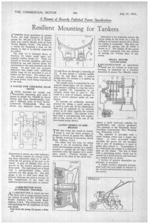
COMING from specialists in vehicles for the bulk transport of liquids, patent No 587,164 is by W. P. Butterfield, Ltd., and G. Mosby, both of Tank Works, Shipley, Yorks. The subject is a means for mounting a tank on the chassis so that it is 'entirely supported by rubber.
The tank (1) is strapped down to brackets (2) which stand upon rectangular rubber blocks (3). These are housed in box-like members, and have bonded-on top and bottom plates for attachment to the tank brackets and the chassis. To deal with any excessive deflection that might arise, additional rubber 'rings (4) are provided to act as buffers on the frame. The scheme prevents stresses, arising from twisting of the main frame, from being transmitted to the tank.
A GAUGE FOR CHECKING GEAR TEETH
A TOOL intended for rapidly and rlaccurately measuring gear teeth is shown in patent No. 586,808 by David Brown and Sons (Huddersfield), Ltd., and I. Milwain, both of Park Works, Lockwood, Huddersfield. With this device, any departurt from standard
dimensions is shown on a dial indicator.
The device consists of a frame carrying three adjustable stops (1, 2 and 3) which fix the position of the gear to be tested. A pair of sfidable jaws (4) is pre-set to the correct distance across three teeth. The right-hand jaw is fitted with a spring-loaded slider which operates the dial gauge (5). The dial gauge is set to read zero when the distance between the jaws is correct, so that irregularities in the teeth are indicated quantitatively (plus or minus).
CARBURETTER WITH AUTOMATIC CONTROL
ACARBURETTER in which the fuel is dealt with at pump pressure forms the subject of patent No. 587,093 from Bendix Aviation Corp., South Bend, Indiana, U.S.A. The carburetter is ilso self-regulating for all conditions of load and speed.
Fuel from the pump (I) passes a fitter
(2) and flows up through a metering jet (3). It then passes a variable needlevalve (4) and flows into a hollow bridge-piece (5) whence it is picked up by the air-stream.
The needle-valve is controlled by two separate diaphragms, one (6), subject to fuel pressure, tending to close the valve, and another (7), responding to air velocity; which tries to open it. The result is a state of balance, claimed to give a correct mixture under all conditions.
To provide an artificially enriched mixturefor idling, a small spring (8) is used to load one of the diaphragms. This can be adjusted by an external screw; in all other respects the control is quite automatic. The scheme works best With a non-pulsating fuel supply; this is the reason for the use of the four-vaned pump shown.
LATEST DESIGN IN DISC BRAKES
THE disc brake has much to recommend it, and the latest practice in design is shown in patent No. 586,582, by Bendix Aviation Corporation, South Bend, Indiana, U.S.A.
The wheel hub has keys (1) which engage a set of revolving discs (2), whilst the backplate carries, in a similar manner, a second set of discs which interleave after the manner of a multiplate clutch. Friction facings are attached to the discs in the usual way. Operation is by hydraulic means, the piston being in the form of a ring (3) sliding in an annular groove (4) to which the piping is connected. The discs are retracted by springs, one of which is shown at 5. The subject of the patent is a detail connected with the method of making the friction discs in segments.
SMALL MOTOR CULTIVATOR
ik /I ECHMHZATION of agriculture IVIneed not be limited to large-scale farming, as instanced by a machine described in patent No. 586,624, which
shows a small cultivator suitable for smallholders and market gardeners. The patentee is the Simplicity Manufacturing Corporation, Port Washington, Wisconsin, U.S.A.
The machine is provided with a small leading wheel and a larger rear wheel. A, little air-cooled engine provides the power for the machine, and a pair of handlebars is used to guide and control it. Transmission is by a belt from the engine to a reduction gear on the wheel. The belt is fitted with a tensioning pulley, which can be moved by a hand control and functions as a simple form of clutch.
A variety of quickly detachable implements is provided.
A simple toolbox clamping arrangement locks the tool rigidly in relation to the vertical and horizontal movement of the tractor.