


UPKEEP OF COMMERCIAL ELECTRIC VEHICLES.
Page 9
Page 10
If you've noticed an error in this article please click here to report it so we can fix it.
[The upkeep of the commercial electric vehicle is not a matter that presents any great difficulty, bat ignorance of the mere fundamentals is largely apt to prevent a matt from attempting to gain the knowledge that would enah:e him to approach the task of driving, tending and maintaining a 'vehicle run under electric power. To assist in that dissemination of knowledge that should serve to develop driving talent tor electric vehicles, we propose to pubtish a very short series of non-technical articits from the pen of a competent electrical engineer. —E D. I IN THE.ELECTRIC „ROTOR used fer driving electrical vehicles, there is a drum called the arma. ture, revolving inside A containing cylinder, in Whichwhat are called • the field magnets are held. The containing cylinder is now usually of a special form of steel that can be cast and will take a high degree of magnetization. The field magnets create What is ealled_a magnetic field, and the armature is made to revolve in this field by electric currents passing through it, and through the wires on the field magnets. -In doing so, the armature furnishes power which is delivered to the driving wheels of the vehicle, sometimes by gearing and sornetinies by
chains. • . .
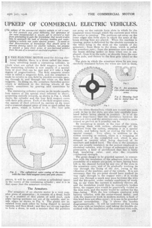
The containing cylinder carries on its-inside-usually four masses of the special steel referred to above, projecting radially inwards as shown in Fig.. 1, which shows the cylinder and the four field magnet cores with their pole pieces. Each of the field magnet cores, the masses of Steel referred to, carries on its inner. end a crescent-shaped piece of iron or steel called the pole piece, which is belted to it. The four pole_
pieces, it will be noticed, enclose a cylindrical space in the centre of the containing cylinder ; and it is in that space that the armature revolves.
The Armature.
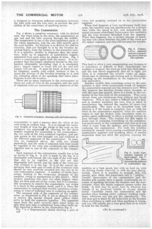
The armature of an electric motor is a very complex piece of apparatus ; it consists of a drum, built up of a number of thin plates of mild steel, each plate having portions cut out of its outside, and inside edges as shown in Fig. 2. The plates are insulated from each other by being dipped in special varnish, and then dried; and they are strung together to form a drum, in such a manner that the portions
cut away on the outside form slots in which lie the insulated wires through -which the currents pass when the motor is running: The portions cut away on the inner edges also forty, slots in which the arms of the brags driVing boss are placed. When the machine is running, Power is .delivered by the electric currents to the wires lying in the slots on the outside of the armature ; from them to the drum, which is called the armature core ; from the armature core either to the brass driving spider or boss when one is employed; from it to the axle or directly from the core to the axle, and thence to axle; first gear wheel or the chain. • 1. The slots in which the armature wires lie are very carefully insulated. before the wires are laid in them, .•
and the wires themselves, Which are wound into coils ready to lay in thd slots, are also very carefully insulated before being placed in position. It is of the ntmost importance that the insulation between the armature wires and the armature core should be .maintained as perfect, as it possibly can be.
By insulating is meant, in the ease of the wires,. wrapping them with cotton; abstracting , all the moisture from the cotton, steeping it in a special varnish, and baking, hard, or coittnig the wire in a special enamel.. Very often, -in addition to the cotton'covering or enamel, there is a wrapping of tape outside of the completed coil, which is also steeped in varnish • after being deprived of its' moisture and baked hard. The slots in the armature core are usually insulated, in the motors employed in--electrical vehicles, with linings of substances such as press-pahn, a kind of pasteboard that has a fairly. high insulating value, and also the requisite mechanical strength.
The great danger to be guarded against, in connection with the insulation of the armature wires is the possibility of a minute pin-pcint, or burr, haling been left in the channel formed by any one of the slots in the armature core, and of its. gradually 'working its way through the lining of the slot, owing to the vibration of the machine, and of the vehicle.It is not necessary that the pin-point should have worked its way right through to the copper wire ; if it weeks part way through a spark may pass between the wire and the tin-point, under certain conditions of working, as say when the current is suddenly thrown off, and the insulation would then be completely broken down, the copper wire would be practically welded to the iron core, and the motor would be useless for the tinielbeing. With the low voltages employed with battery vehicles, with the series-wound motor, and with the improved work in modern, motors, a fault of this kind does not often occur ; it. is one to be guarded against nevertheless. Fig. 3 shows the trouble diagrammatically. It will be understood that lining the slots with an insulator, and taking the trouble described with the insulation of the armature wire coils, is designed to interpose sufficient resistance between the wire-coilsand the iron core, to prevent the possibility of the occurrence of sparking across.
The Commutator.
Fig. 4 shows a complete armature, with its slotted core, the wires lying in the slots, the commutator at one end and the axle running through the middle. The commutator is one of the most important parts of the whole apparatus, and the one that usually gives the Most trouble. Its function is to deliver the electric currents, that are brought to it by the brushes described below, from the battery to the armature coils. It is a cylinder, smaller in diameter than the armature, built up Of segments of hard-drawn copper, separated from-each other by plates of mica. Fig. 5 shows a commutator apart from the motor. It is important that the copper employed should be the very hardest obtainable, providing that it is absolutely pure ; impure copper or brass will not do, and soft copper will not do. It must be hard, as hard as can be obtained, usually cold rolled, because it has to stand. the friction of the brushes pressing on it, and the softening effect of the sparking that takes place between it and the brushes. • There are as many 'segments in the commutator as there are coils of wire on the armature, and the ends of adjacent coils are connected to the segments of the commutator, in such a. manner that the whole of the coils forna an endless wire. It is as though the necessary length of wire for the whole of the coils on the armature was measurad off, allowing for the short lengths required for connecting to the commutator ; the two ends of the wire soldered together, and certain points in the wire brought out and soldered to the different segments of the commutator. In practice, as explained above, the coils are wound geparately, and the ends of adjacent coils that would he together if the wire was continuous are soldered together and to one of the segments of the eommu tator. •
Each segment of the, commutator usually has a lug as shown m Fig. 6. A slot is made in the lug, it is thoroughly well tinned, the two ends of the wire coils that are to be together in the slot are also thoroughly well tinned, and the ends of the wires are well sweated in to the lug. It ia4of the utmost importance that each pair of ends of the armature coils should be very carefully sweated into the slot in its own commutator segment. A number of faults have arisen, leading to the temporary stoppage of the machine, owing to carelessness in this matter. With modern machines this does not often happen when they are first sent out of the works, but it is occasionally necessary to remove the commutator, say owing to a fault in the armature itself, and it is when the commutator is replaced that trouble sometimes arises, owing to wanty■f sufficient care in soldering up again. The recessed ends of the segments of the commutator, as illustrated in Fig. 6, are so shaped in order to receive the special shaped steel collars which serve to hold the segments together. The segments taper from the outer towards their inner faces, so that they may take a cylindrical form.when built up. This tapering is shown in the illustration Fig, 6.
• Fig. 7 is .a diagrammatic sketch showing a pair of 530
wires not proprerIy sweated on to the commutator segment.
When that happens a very troublesome fault May arise, the machine may run satisfactorily for a certain time while the speed is low, and immediately the speed increases centrifugal force comes into operation arid the wire becomes detached from the segment. When that happens, too, a c..ertain..amount of sparking may take place between the ends of the wires and the copper segment, and that will increase the trouble.
This fault is often a very exasperating one, because it is sometimes so difficult to find ; nnmediately the machine is stopped-, the wires go back. into their place, and the test shows apparently that all. is right, yet when it is restarted the trouble comes. up again.. Great care in cleaning,and tinning and in thoroughly . sweating up the connections at the -segments is the only preventive. Another trouble that sometimes arises to the commutator is. that wires occasionally break of between the commutator segment and the armature core, When this happens the machine breaks down, because, as with the case just quoted, there is a break in the continuity of the wire coils on the armament. They must always form one continuous, loop without any break .whatever. This is also rather a difficult fault to find, and in modern machines the care that is taken in -manufacture has reduced the number of cases very considerably. The tests to be described later will disclose it if the break is complete, but, as with the Wires in the commutator segment, when the machine comes to rest the broken ends 'sometimes come together again suffieiently to allow a testing current to pass through them. The remedy for this again is great care in replacing everything 3n the armature, and particularly at the commutator end, just as it was when it came from the makers, after removing and replacing the commutator. For -both the troubles mentioned, namely wires coming unsoldered from the commutator segment and breaking short, if careful inspection does not show the position, running the machine at a high speed, but with no load on, with the driving -chains removed, or with the gear disconnected, where it is possible to arrange this, will usually give what thes Americans call a " pointer." Careful observation of the commutator and the brushes will usually show a spark, occasionally an increase of sparking between the brushes and the commutator, when the faulty segment passes under the brush. A hint may be given here to whoever has -charge 'of an electrical vehicle or of ,i;any electric, motor. Carefully watch the commutator and the brushes when running under ordinary working conditions, whenever you can get the opportunity. You will soon get to know by, the behaviour at the brushes then everything is right and when anything is wrong, and you will usually get a very good hintas to where to look for the trouble.
(To be continued.)