


With Intent to Improve.
Page 26
If you've noticed an error in this article please click here to report it so we can fix it.
A Weekly Summary a Recent Patents, of Interest to the Maker and User of Commercial Motor Vehicles.
The Holt Manufacturing Co., of California, is prolific in invention and patent for the improvement of its well-known product the caterpillar tractor. An interesting example before us this week relates to the Suspension of the chassis of this tractor on the framework which itself is carried by the endless tracks from which the vehicle gets its name. In a machine of this kind designed for the express purposnof travelling where roads are non-existent, and, therefore, subject to the very considerable stresses and strains due to its passage over uneven ground, the suspension of the mechanism in such a manner that it suffers as little as possible from these stresses is a matter for careful consideration. In the patent under discussion a rather ingenious three-point suspension has been invented. Our illustration shows only the single pivot arrangement for the front end of the chassis of the tractor.
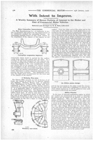
A Wolseley Non-skid. • The Patent Office records are full of devices of all kinds, the objects of which are to prevent sideslip and skidding. Wolseley Motors, Ltd., of Adderley Park, Birmingham, in Patent No. 16,306, 1915, have registered a device which besides having features novel even for a patent, also has many to recommend it. It is applicable either to rubber-tired wheels or to wheels having metal tires. Our illustration shows it as applied to a motor lorry wheel fitted with twin rubber band tires. It will be seen that it consists of a number of corrugated plates of special shape. One end of each plate is bent over...so that its inner surface beds on the inner side of the rim of the wheel and presents to the rim a taper or wedge form of sueface. Near the other end of this plate and .9A the other side of the wheel rim a bell *rank lever is attached by' the upper end of a vertical arm, which arm also bears on the outside rim of the wheel. The other arm is horizontal and serves for the attachment of a chain, the inner end-of which is fastened by means of a hook, or plate with hooks embodied, on to bolts in the nave of the wheel. In the length of this chain is fitted a turn-buckle, so that the chain may be tightened or so that sufficient slack may be allowed to permit of its removal from the hooks. A study of the drawing will make it clear that by tightening the chain the horizontal arm a the bell crank lever is pilled downwards, the vertical arm bears on the outside edge of the rim of the wheel as on a fulcrum and tends to pull the corrugated non-skid plate in such a direction that that portion of it which presents the *edge-form surface to the under and inner side of the rim automatically tightens upon the rim. The plate is thus secured in position on the wheel,
and as any movement in the plate round the circumference of the wheel has a tendency to shorten the chain which secures it, it will be gathered that such movement is effectively prevented.
• Albion Pistons.
In the type of internal-combustion engine to which our readers are accustomed it is usual to lubricate the piston pin by means of oil thrown up from the inside crankcase. This oil falls upon the inner surface of the piston and drops on to the upper end of the connecting rod, which is usually provided with a recess at its top end and a hole, which allow the passage of the oil through the bush to the surface of the pin. The Albion Motor Car Co., Ltd., Sectstom, and Thomas Blackwood Murray, have patented an arrangement of a piston for internal-combustion engines which allows of a more positive means of lubricating this bearing. A shallow groove round the piston cut midway between the position occupied by the lower piston ring and the gudgeon pin itself serves to collect the oil. At two points in the piston wall holes are bored connecting this groove with the interior of the piston. In one arrangement these two holes are joined by a piece of tubing, which itself is drilled midway along its length, so that any oil collected from the cylinder walls and deposited in this groove passes thence along the tube and emerges from this centrally disposed hole, falling into a recess in the connecting rod. In an alternative arrangement suitable passages are cast in the piston itself