


Quicker Emptying for Tankers
Page 50
If you've noticed an error in this article please click here to report it so we can fix it.
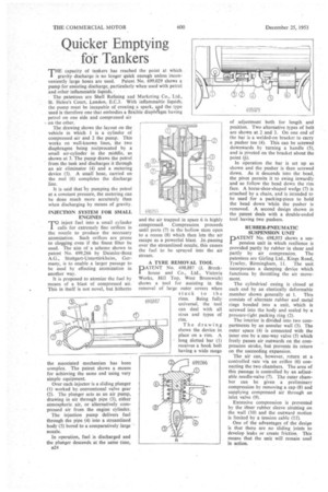
THE capacity of tankers has reached the point at Which gravity discharge is no longer quick enough unless inconveniently large hoses are used. Patent No. 699,029 shows a• pump for assisting discharge, particularly when used with petrol and other inflammable
The patentees are Shell Refining and Marketing Co., Ltd., St. Helen's Court, London, E.C3. With inflammable liquids, the pump must be incapable of creating a spark, azd the.type used is therefore one that embodies a flexible diaphagrn having petrol on one side and compressed air on the other.
The drawing shows the layout on the vehicle in which 1 is a cylinder of compressed air and 2 the pump. This works on well-known lines, the two diaphragms being reciprocated by a small air-cylinder in the middle, as shown at 3. The pump draws the petrol from the tank and discharges it through an air eliminator (4) and a metering device (5). A small hose, carried on the reel (6) completes the discharge line.
It is said that by pumping the petrol at a constant pressure, the metering can be done much more accurately than when discharging by means of gravity.
INJECTION SYSTEM FOR SMALL ENGINES
rinject fuel into a small cylinder calls for extremely fine orifices in the nozzle to produce the necessary atomization. Such orifices are prone to clogging even if the finest filter be used. The aim of a scheme shown in patent No. 699,266 by Daimler-Benz A.G., Stuttgart-Untertiirkheim, Germany, is to enable a larger passage to be used by effecting atomization in another way.
It is proposed to atomize the fuel by means of a blast of compressed air. This in itself is not novel, but hitherto the associated mechanism has been complex. The patent shows a means for achieving the same end using very simple equipment.
Over each injector is a sliding plunger (1) worked by conventional valve gear (2). The plunger acts as an air pump, drawing in air through pipe (3), either atmospheric air, or alternatively compressed air from the engine cylinder.
The injection pump delivers fuel through the pipe (4) into a streamlined body (5) bored to a comparatively large nozzle.
In operation, fuel is discharged and the plunger descends at the swine time, u24 and the air trapped in space 6 is highly cOmpressed. Compression proceeds until ports (7) in the hollow stem open to a recess (8) which then lets the air escape as a powerful blast. In passing over the streamlined nozzle, this causes the fuel to be sprayed into the air stream.
A TYRE REMOVAL TOOL DATENT No. 698,887 (J. Brock house and Co., Ltd., Victoria Works, Hill Top, West Bromwich) shows a tool for assisting in the removal of large outer covers when stuck to the rims. Being fully universal, the tool can deal with all sizes and types of rim.
The drawing shows the device in place on a rim. A long slotted bar (I) receives a hook bolt having a wide range
of adjustment both for length and position. Two alternative types of bolt are shown at 2 and 3. On one end of the bar is a welded-on bracket to carry a pusher toe (4). This can be screwed downwards by turning a handle (5), and is pivoted on the bracket about the point (.6).
In operation the bar is set up as shown and the pusher is then screwed down. As it descends into the bead, the pivot permits it to swing inwardly and so follow the bead down the rim face. A horse-shoe-shaped wedge (7) is attached by a chain, and is intended to be used for a packing-piece to hold the bead down while the pusher is removed. A second design shown in the patent deals with a double-ended tool having two pushers.
RUBBER-PNEUMATIC SUSPENSION UNIT
PATENT No. 698,953 shows a suspension unit in which resilience is provided partly by rubber in shear and partly by air compression. The patentees are Girling Ltd., Kings Road,
Tyseley, Birmingham, 11. The unit incorporates a damping device which functions by throttling the air movement.
The cylindrical casing is closed at each end by an elastically deformable member shown generally at 1. This consists of alternate rubber and metal rings bonded into a unit, which is screwed into the body and sealed by-a pressure-tight packing ring (2).
The interior is divided into two compartments by an annular wall (3). The outer space (4) is connected with the inner one by a one-way valve (5) which freely passes air outwards on the compression stroke, but prevents its return on the succeeding expansion.
The air can, however, return at a controlled rate via an orifice (6) connecting the two chambers. The area of this passage is controlled by an adjustable needle-valve (7). The outer chamber can be given a preliminary compression by removing a cap (8) and supplying compressed air through an inlet valve (9),
Excessive compression is prevented by the Miler rubber sleeve abutting on the wall (10) and the outward motion is limited by a tension cable (11).
One of the advantages of the design is that there are no sliding joints to develop leaks or create friction. This means that the unit will remain cool in action.