


Servo Principle in Implement Lift Gears
Page 36
If you've noticed an error in this article please click here to report it so we can fix it.
PATENT No. 548,451 deals with hydraulic lifting gear for ploughs, cultivators and other tractor-drawn implements. The patentees are David Brown Tractors, Ltd., and H. E. Merritt, both of Meltham Mills, Meltham, Huddersfield. Such lifting gears, the patenteds state, usually permit only the rise and fall of the implement, and will not maintain it in
a n intermediate position. To fulfil
this latter requirement is the object of the improved design, the action of the ram plunger following the motion of the controlling handle. on the servo principle.
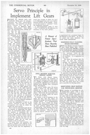
Numbered 4 in an accompanying drawing, the power piston is connected with an implementlifting shaft (9) and is moved by hydraulic pressure from an enginedriven pump (5). Control is effected through the medium of a valve (6) operated partly by manual means and partly by the implement-lifting gear.
The controlling handle (8) has • an extension incorporating a cam face (7) associated with a roller on the end of a lever (2). This lever is pivoted on the spindle of the valve (6) and is coupled at its other end to a link (3) attached to the arm of the lift shaft.
Considering the operation of the mechanism, we must first visualize the control handle (8) to be set, not as shown, but in a midway or vertical position, with the roller against face 7. Movement to the right depresses valve 6, closes exhaust part 10 and discharge port 11, and causes fluid to flow into the ram. Motion of handle 8 to the left has the reverse effect. Likewise any upward or downward travel of the ram piston (4) immediately moves (via link 3 and lever 2) the valve (6) in the direction necessary to create a restoring force.
Thus the implement is held inth'e position, whatever it may be, which corresponds with that to which the handle has been moved.
Rod 1 and its associated pawl are for the purpose of supporting the implement, by mechanical means, when at the position of maximum lift. As drawn, the roller has passed over the maximum-Plift position (shown dotted) of the cam, so that the valve (6) has opened and allowed the arm on the implement shaft (9) to sink just enough to rest on the pawl.
To lower from this position, the handle is shifted a few degrees to the left and its first action closes the valve, with the result that the implement is raised just enough to allow the pawl to be disengaged (via rod 1) by further leftward motion of the handle. Then, as the last-named is " notched " back, the implement descends.
A not-unimportant point is that " feel " is afforded by the difference in diameters of the valve pitons.
taneous precision the moments of opening and closing is the chief object of a design a injection nozzle shown in patent No. 548,454 by G. Orloff and Rubery Owen Messier, Ltd., Liverpool Road, Warrington.
The central needle valve (2) moves within a sleeve (1), the latter being slidabIe in the body of the injector, and forming, in effect, an accumulator piston. The needle (2) is provided with a flange (4) against which the sleeve (1) can abut if lifted.
In action, a rise of pressure in the space (8) first _lifts the sleeve (1) against its spring, the needle, however, remains seated. At a predetermined height, the sleeve strikes the flange of the needle, knocking it suddenly into its open positionagainst the usual closing spring. Fuel pressure then, acts on both members for so long as the injection continues. When the pump ceases to deliver, pressure in space 3 is maintained for a moment longer by the 'descent of the sleeve. So soon as its coned end seats, however, the needle shuts immediately'.
INGENIOUS FULLY FLOATING BRAKE EXPANDER
FROM the Bendix Aviation Corporation, South Bend, Ind., U.S.A., comes, in patent No. 6'48,207, a design for an hydraulically operated floatingshoe brake of simple construction. Two sectional views of the operating mechanism on one side are included. It is duplicated on the other,
The drum (5) encloses only the links (7) and the retracting springs, the hydraulic actuators (1) being located on the oubaide of the backplate (3). When the brake is out of action, the shoe webs (4) abut on an anchor plate (6), but during braking one or the other leaves the anchor.
In operation the hydraulic actuators spread the levers (2), slots in the backplate allowing room for them to move and the levers, in turn, separate the shoes by pressure on the webs (4). Being joined, however, by the links (7) they can freely move as a whole and so provide the floating action.
SHEET-STEEL HEAT BAFFLES FOR PISTON-RING GROOVES
T"practice of providing an alu• minium-alloy piston with a steel ring-carrier is well-known, but such inserts, being usually machined from the solid, may he somewhat expensive items. An equally efficient 'but cheaper method of construction is shown in patent No. 548,400 bY Hepworth and, Grandage, Ltd.. and L. Howell, both of East Bowling,Bradford.
Several variations of the scheme are described, one of which we illustrate. A U-section ring of sheet steel, Y6 in. thick, for example, is cast into the alloy piston and retained by the metal which flows through holes in the back of the ring. In this case, the housing supports the piston-ring both above and below, but in another instance, the ring-groove has only a steel bottom,
Chief object of the insert is to act as a heat baffle and prevent the high piston temperature from reaching the rings. Therefore, the steel does not necessarily have to make direct contact with the ring.