


Automatic Clutch for Large Engines A Resume of Recently Published
Page 46
If you've noticed an error in this article please click here to report it so we can fix it.
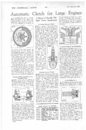
Patent Specifications ACENTRIFUGAL clutch, controlled by the speed of the engine, and specially designed for use with oil and other large power units, is shown in patent No. 456,710 by Schneider et
Cie., and J. Fienx, both of 42, rue d'Anjou, Paris. In this design, the bob-weights are made in two sets, one of which is pivoted on pins (5) fixed to the flywheel, whilst the second set pivots about other pins (3) connected with a floating band (2). The two sets are interconnected by pins 4, so that the outward movement of the weights exercises a scissor-like movement and draws pins 3 and 5 apart.
The floating band (2) is a helically split drum, and the angular movement of the two sets of pins has the effect of increasing its diameter, thus exerting a pressure on the friction lining. The restoring force is provided by a system of coil-springs (1), which also tend to damp out torsional oscillations.
Housing a Filter in the Base of an Injection Pump.
SPACE saving and the absence of exterior piping are the chief features of a filter layout shown in patent No. 457,069 by Automotive Products Co., Ltd., D. T. Brock, and G. J. Trapp,
all of Brock Ifouse, Longhorn Street, London, W.1. As shown in the drawing, the filter (2) is located in the base of the pump, and is made with a small thickness but with an area approximating to that of the pump base. The filter slopes upwardly from the centre of the pump, and terminates in the inlet pipe (3). The feed pump (1) draws fuel through the filter and delivers it straight to the plunger system, thus the assembly is a unit without exterior pipes and unions.
a40 A German Injection Pump.
FROM F. Deckel, 7-13, Waakirchnerstrasse, Munich, comes patent No. 456,508, giving details of an improved assembly of the output control of an injection pump. The patent stat-s that, whilst for the sake of compactness, it is desirable to house the main sliding member inside the control sleeve, any attempt at a close fit will cause jamming of the control sleeve owing to the side thrust of the cam.
In the pump illustrated, the control rack (6) turns a sleeve-pinion (5) which is slotted for the reception of a pin (2) projecting from the foot of the plunger; thus is the control motion transmitted to the plunger. The basis of the patent is that the main slider (4) is guided in a bush (3) at the lower end, and a bore (1) at the top; this leaves the pinion (5) in a clearance bore so that jamming cannot occur.
Priming Injection Pumps.
COME injection pumps are fitted with Oa hand lever to each plunger, so that
an initial charge of fuel may be passed through the pump before starting the engine. To abolish this extra mechanism, and yet retain the benefits thereof, is the object of the scheme shown in patent No. 456,239 by Automotive Products Co., Ltd., Brock House, Longhorn Street, London, W.1, and G. J. Trapp, 105, Aylward Road, London, S.W.20.
The scheme aims at permitting hand rotation of the camshaft cf the pump. This necessitates a disconnection of the driving arrangement, which is achieved in this case by the use of a free wheel in the drive. To ensure the resumption of the correct timing relationship, the free wheel has but a single tooth for the driving pawl to engage. The pump is hand rotated by means of a wheel on the non-driving end, although a rocking lever and ratchet, or a worm and worm-wheel, are also suggested, the object being to afford a mechanical advantage.
A Catalytic Igniter for Oil Engines.
TO enable an oil engine to be run on low-grade fuel is the object of the invention shown in patent No. 455,329 by Gesellschaft Fiir Teerverwertung m.b.H., Duisburg-Meiderich, Germany. As will be seen from the accompanying drawing, the pocket containing the injector is lined with a special sleeve ; this is made of a catalytic material, such as salts of the metals chromium.. nickel, molybdenum, and osmium.
According to the patentee, this sleeve is not intended to have any effect on the injected fuel, but is for the purpose of exercising a hydrogenating effect on the exhaust residue remaining in the sleeve. Thus, it is claimed, a small amount of light hydrocarbon vapour is formed in the pocket during each compression stroke, and this ignites at a lower compression, and initiates the combustion of the main fuel charge.
A Novel Filter Unit.
A FILTER for insertion in the pipelines of injection nozzles is shown in patent No. 456,754 by L. Griffiths
and the British Thomson-Houston Co., Ltd., Crown House, Aldwych, London, W.C.2. The filtering medium consists of a coil of strip metal (2) through which the fuel flows, entering at holes 3 and leaving via groove 1.
The unit is easily demountable for cleaning, an operation which consists of removing the strip, wiping it, and re-coiling before insertion. The use of strip allows a restricted width of passage and a sufficient surface area to avoid throttling the fuel supply..