


A NEW TYPE OF VALVE GEAR
Page 28
If you've noticed an error in this article please click here to report it so we can fix it.
A Résumé of Recently Published Patents.
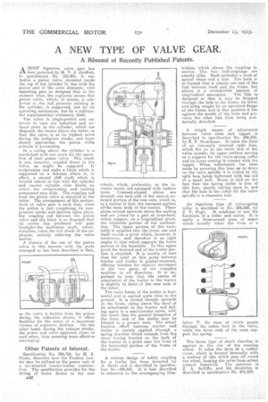
AMOST ingenious valve gear has been patented by H. V. J. Jouffret, in specification No.. 191,401. It em-. bodies a piston valve, mounted _inside the top of the cylinder In line with the piston and of. the smilediaineter,_ with operating gear so designed that at the moment when the explosion occurs this piston valve, which, of course,, is sub-_ jeated to the full pressure existing in the cylinder, is supported, not by its operating mechanism, but by a substanCa/ supplementary stationary shaft.
The valve is single-Ported and uncovers in turn the induction and exhaust ports in the cylinder, which are disposed, the former above the latter, so that the valve. is at its highest point during the induction stroke, and more closely approaches the piston while exhaust is .proceeding.
In a cueing above the cylinder is a crankshaft with one crank for the operation of each piston valve. This crank is. not, however, coupled direct to the valve, as 'might be supposed. It' reciprocates 'and rocks a block which is. supported on a fulcrum which is, in effect, a second stiff shaft which is located almost in line with the cylinder and carries suitable slide blocks on which the reciprocating and rocking component may slide. The coupling rod from the piston valve is attached to the latter. The arrangement. of this motionwork or valve gear is. such that, when the piston is just. completing its compression stroke and ignition takes place, the coupling rod between the piston valve and the block is so dieposed that its centre line produced will pass threughe the stationary shaft, which, 'therefore, takes the full shock of the explosion, entirely relieving the valve. motion.
A .feature of the use of the piston valve in this manner with the ports arranged as has been described is that,
as the valve is farther from the piston during the induction stroke, it offers facilities for the entry of a maximum volume of explosive mixture. On the other hived, during the exhaust stroke, the piston and valve approach closer to each other, thus ensuring more effective scavenging.
Other Patents of Interest.
Specification No. 206,766, by H. J. Casey, describes how the Fordson tractor may be utilized as the power unit of a six-wheeled tractor-trailer combinaVon. The specification provides for the fitting of brake drums to the rear
248
wheels, which, preferably, as the inventor states, are equipped with cushion tyres. Crescent-shaped plates are secured, one each side of the central.enlarged portion of the rear axle, ivhieli is, as a matter of fact, the rearmost portion oftthe main body of the tractor. These plates extend upwards above the casting and are joined by a pair of cross-bars, which support, on a longitudinal pivot, the turntable portion of the combination. The upper portion of this turntable is spigoted into the lower one and itself carries a pivot which, however, is transverse, and therefore is at right angles to that which supports the lower portion of the turntable. ro this upper pivot the forward end of the trailer portion is.. attached. It is worthy of note that, the joint at this point between tractor and trailer is gimbal-mounted, offering freedom for relative movement of the two parts of the complete machine in all directions. It is important to note that the centre of attachment of the. trailer to the tractor is slightly in front of he rear axle of the hittee.
The main frame of the trailer is horizontal and is carried quite close to the ground. It is turned sharply upwards at. the front, rising above the level of its attachment to the tractor and falling again in a semi-circular curve, with the result that the general formation of the front end of the trailer may be likened to a goose's neck. The actual tractive effort between tractor and trailer is Mainly applied through a spring drawbar which extends from the usual towing bracket on the back of the tractor to a point near the front of the horizontal portion of the frame of the trailer.
A curious design of safety coupling for a trailer has been invented by A. Santa and is described in specification No,.206,681. It is best described in reference to the accompanying illus
tration, which shows the coupling in , section. The two half-couplings are ' exactly alike. Each 'embodies a hook of special shape and a link. The hook is so formed that, it retains one end of the link between itself and the frame, but allows it a considerable 'amount of longitudinal movement.. . The link is designed so that it. may be dropped through the hole in the frame, its lower end being caught by an upturned flange of the frame, and in that position it lies against the month of the hook and prevents the other link from being accidentally detached.
A simple means of adjustment between valve stem and tappet is described in specification No. 206,575, by E. F. Struckman. It takes the form of an internally screwed split, bees, which fits on to the lower end of the valve spindle, its upper surface serving as a support for the valve-spring collar and its lower coming in centact with the tappet. When adjustment has been made by screwing this bass up or down on the valve spindle itis locked by the split boss being tightened with the aid of a small bolt. Stress is laid on the fact that the spring collar is free of this boss, merely resting 'upon it, and that the hole in the collar for the valve spindle is a clearance hole.
An ingenious type of valve-spring collar is described in No. 206,580, by J. V. Pugh. It combines in one the functions of a collar and cotter. It is really a three-armed piece of metal which broadly takes the form of a
letter T, the stem of which passes through the cotter hole in the valve, while the three ends of the arms support the spring.
The latest typeof shock absorber is applied to the rim of the steering wheel. It takes the form *A a rubber cover, which is formed internally with . a number of ribs which peas all round. the wheel, keeping the 'cover from actual contact therewith. The patentee is J. A. Sutliffe, and his invention is described in specification' No. 206,527.