


Air-operated Gear Changing
Page 78
If you've noticed an error in this article please click here to report it so we can fix it.
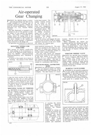
PATENT No. 869,264 shows a poweroperated gearchange unit that can be readily attached to a normal type of manually operated gearbox, without the need for serious modifications. (Clayton Dewandre Co., Ltd., Titantic Works, Lincoln.)
The unit illustrated is intended to be mounted on top of the gearbox so that the striker (1) can operate the selector forks. The striker is controlled by an annular piston (2) sliding both in the cylinder casing and on a central sleeve (3). The sleeve extends to the outside and forms the control member, a hand-lever being connected to the flange (4). , In operation, the hand-lever is operated in the usual manner. The angular rocking motion of the striker is still done by hand, but the actual gear engagement is power assisted through the annular piston. The hand-lever, at the start of its sliding movement, causes one or other of the valves (5 and 6) to be unseated. This admits compressed air to one side of the piston, and engages the gear.
In the event of failure of the air supply, continued movement of the lever would still engage the required gear.
ROTATING NEEDLE FOR INJECTORS
T°prevent an injector needle-valve from seizing, in all circumstances, is the, aim of an improved nozzle shown in patent No. 868,093. (Maschinenfabrik Augsburg-N0mberg A.G., NUrnberg 2, Germany.)
A section of the nozzle tip is shown inthe drawing. The essence of the scheme
-s that the lower portion of the valve is helically cut into one or more grooves (1). The fuel entering the port (2) is said to impart a rotary motion to the valve. The contact face (3) of the loading spring is made as small as possible to avoid impeding the rotation.
MOUNTING TANKS ON VEHICLES
r1A METHOD of mounting a large tank on a chassis is shown in patent No. 867,360. (Luther-Werke, Luther and Jordan, Frankfurter Strasse 249/255, Braunschweig, Germany.)
The drawing shows a plan view of the resilient units used. Welded to the tank are V-shaped brackets (1). The inclined faces of the brackets fit into a rubber/ metal sandwich mounting (2). The outer plates are attached to the frame by central bolts (3) which have beneath their heads a number of Belleville washers to provide extra vertical resilience.
The four units shown are disposed symmetrically about the centre of gravity of the tank, shown at 4. The front member (5) is a ball-and-socket joint also bushed with rubber. The duty of this unit is to resist the longitudinal forces created by acceleration and braking.
ROLLER-BEARING CONNECTING RODS
DATENT No. 869,326 shows a connect' ing rod designed mainly for diesel engines which have roller bearings at the crankpins. The chief feature is a means
of locating the halves
positively. (Motorenfabrik Hatz G.m.b.H., Ruhstorf bci Passau, Germany.)
Instead of relying on the bolts for location, the mating surfaces of the connecting rod halves have close-fitting serrations as shown at (1). These, when bolted firmly together, form a positive and repeatable location. Dowels (2) are used to give axial location.
When assembled, the halves are hardened and the bore finished by grinding. This eliminates the need for a separate hardened sleeve. Care is taken to avoid hardening the serrations to prevent the risk of fracture through their being brittle.
INJECTOR NEEDLE VALVE
PATENT No. 862,383 from Caterpillar Tractor Company, 800 Davis Street, San Leandro, Cal., U.S.A., shows an injector valve made in the form of a sliding plunger instead of using mating seatings. The advantages claimed are reduced likelihood of damage and better protection from heat.
BI-METAL VALVE GUIDES
ASCHEME for the quantity production of valve guides with improved wearing qualities is described in patent No. 869,384. (The Glacier Metal Co., Ltd., 368 Ealing Road, Alperton, Wembley.) The drawing shows a section of the proposed guide in a cylinder head. It is formed initially from .a bi-metal strip with steel on one side and bronze or other bearing material on the other. The strip is rolled into a tube, with the steel on the outside and the ends pressed together hydraulically to create a flange (I). This acts both as a stop face on the cylinder block and as an abutment for the spring. In addition, a circumferential groove may be left inside the flange to function as an oil reservoir.