


AN IMPROVED FORM OF BRAKE ADJUSTMENT.
Page 28
If you've noticed an error in this article please click here to report it so we can fix it.
A Re'sum4 of Recently Published Patent Specifications.
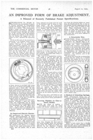
SPECIFICATION No. 231,439, by Societe des Automobiles Peugeot, of France, describes an arrangement suitable for brakes applied to the front wheels of a vehicle. The arrangement shows a brake actuated by MCALIS of chains passing over pulleys. The chain so arranged passes through the hollow pin of the steering head and actuates the rocking lever shown in the illustration by raising the cupped end (A), which, in turn, operates the expanding cam.
So far as this part of the invention is concerned, it is, perhaps, better suited to private cars than to commercial vehicles. The part of the specification which particularly attracted our attention as being a desirable feature which might commend itself to makers of commercial vehicles is the form of adjust' ment for the brake-shoes. It will be seen that the hinge of each shoe is formed like an eye-bolt, being screwed into a revolving sleeve flanged at both ends and running within a boss. Each
of these sleeves is provided with worm teeth cut in its flange and capable of engagement with a worm (B). By this means a simultaneous adjustment of the brake shoes can be made for wear. An adjustment at this point is what should be provided on every brake intended for serious work, as it brings the shoes into proper contact with the drum, instead of at the point of the shoe, as with the ordinary form of adjustment.
The method referred to in this specification, although a good one, seems costly and complicated, and we think we have seen other arrangements which will accomplish the same effect more easily. In the matter of brakes, however, a trifling extra cost should not be a barrier' against the attainment of efficiency.
An Improved Electric Starter.
IN specification No. 224,513, Robert
Bosch Aktiengesellschaft, of Stuttgart, describe a device which they claim is an advance on the usual arrangement of starter pinion. The argument put forward in favour of this device is that, with certain existing forms of starter, the release of the pinion is so sudden, owing to the rapid acceleration of the engine, that the pinion will, in some cases, rebound into mesh with the teeth on the flywheel, and, in doing so, may eause injury. By the arrangement shown in the accompanying illustration it is claimed that the engine, when started, is prevented from tending to accelerate the starter beyond the speed
imparted to it from its source of electrical energy. At the same time, the reooil spring is prevented from being released too suddenly.
The view is a longitudinal section, from which it will be seen that the starting motor is provided with field magnets, which, at starting, bring the pinion into mesh with the teeth on the flywheel in the known manner. The armature is held laterally displaced against the attraction of the field pole by means of the recoil spring shown, but only so long as the pull of the pole On the armature does not exceed the pull of the spring.
The shaft (A) is made hollow at both ends—at the right to receive the recoil spring, and at the left to receive the shaft (B), which carries the pinion. A helical spring is provided, which, at one end, is attached to the shaft (A), but is not positively attached to the shaft (B). A central bolt compresses this spring so that it sets up a certain amount of friction with B ; this friction is increased • when A is driven in a direction which tends to expand the spring and diminishes when the direction is reversed. In other words, it forms a free wheel which prevents the engine from speeding up the starter beyond its own speed.
Springs have been used before to obtain a free-wheel action, as seen in the check spring used in many gramophones.
Securing Rigidity on Char-abancs Bodies.
wim the object of making a thoroughly rigid body for motor coaches and similar vehicles and, at the same time, bringing the floor level to the lowest possible point, the following plan forms the subject of patent No. 237,110 by the Northern Counties Motor Co., Ltd., of Wigan. As will be seen from the drawing which we reproduce, the floorboards lie flat on the actual chassis, thereby dispensing with the bearer so often used in bodies of this --type. These floorboards extend, as shown, on both sides, where they are united by means of longitudinal naembers.•. A board standing up on edge under each seat gives great' stiffness to the construction.
, A Detachable Rim,
STAHLWERK Werner Aktiengesell schaft, of Erkrath, Germany, show in specification No. 237,189 what is described as a new method of obtaining a detachable rim. Most "inventions." that hail from Germany create the impression in our minds that we have seen something very much like them before which has been created by the brain of an Englishman, an American, or a Frenchman, and the present idea is no exception. We, however, give it for what it is worth.
It will be seen from the accompanying drawing that the spokes are so formed that they will engage the rim so far as two of the arms are concerned, but the third one ends short of the rim, so that when the blocks (A) are inserted between it and the rim the latter is secured, It will be seen that the blocks are formed in halves, and are clamped together by means of the bolt shown. Conical faces are provided so as to ensure a better grip.
A Method of Attaching Springs, TEE International Motor Co., 'of
America, deseribe in specification No. 237,175 what is claimed to be a new method of attaching springs to thy frame of a vehicle. We do not know on what principle patents such as this are granted, but,unless we are mistaken, the plan is by no means a new one The spring is attached to the hanger by means of a strip of flexible material such as belting. At the other end buffer of rubber, or some yielding material, is clamped by means of a cap to the -upper part of the chamber. This is said to hold the end of the spring so securely that it will not slide out of its grip. We think, however, that some other means of holding the spring in place endways will probably be found necessary.
There is little doubt that a flexible material such as that suggested would helptowards silence and a reduction of the parts requiring lubrication.