


TWO PECULIAR SPRINGING SYSTEMS.
Page 30
If you've noticed an error in this article please click here to report it so we can fix it.
A Résumé of Recently Published Patents.
L. S. de Richelle and J. B. M. Stanfield appear both to have the same object in view, according to patent specifications Nos. 162,248 and 176,580 respectively, yet the means by which they hope to attain those-ends differ one from another as widely-as one would think possible in all the.circumetances. Both specifications relate to chassis suspension. In both the underlying idea appears to be that of distributing the shock which any indivi' dual wheel may receive over as much of the chassis as possible. There, however, the similarity ends.
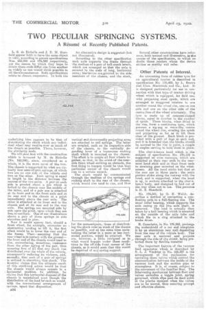
We will,deal first with the construction which is favoured by M. de Richelle (No. 162,248), since, considered as a whole, it is the more novel of the two. The chassis is supported by what are virtually four semi-elliptic springs, of which two are on one side of the vehicle and two on the other. Each spring is equal in length to the distance between the centres of the two axles. A pair on each side is pivoted about a pin which is bolted to the ehassie near the middle of the latter, and of a pair one is attached at its front end to the front axle and at its rear end to the chassis at a point immediately above the rear axle. The other is attached at its front end to the chassis and, at its rear end to the rear axle. The springs are mounted side by side upon the pivot, upon whirls they are free to oseillate. One of our illustrations shows a pair of these springs in side elevation and in plan. Now it would appear that, should a front wheel, for example, encounter an obstruction tending to lift it, the first effect would be to lower the rear end of Ahe frame. Then—assuming that the rear wheel is in contact with the ground— the front end of the chassis would tend to rise, encountering, meantime, resi.stance from the other spring of the pair, thus ensuring first of all that any shock was diatributed.over the whole of the vehicle, consequently reducing its violence, and, secondly, that each of a pair of springs is utilized in absorbing that shock. The • inventor claims that the ultimate result of this combined action would be that the chassis would always remain in a horizontal position. In addition, he • claims that this horizontal disposal of the chassis is maintained even though the distribution of the load be such as would, with the conventional arrangement of springs, upset that disposition.
*34 An alternative design is suggested (but not illustrated).
According to the other specification each axle supports the frame through the medium of a pair of bell-crank levers, which are arranged so that the axle is secured to the ends of long, horizontal arms ; theievers arejpivoted to the side _ members of the chassis, and the short, vertical and downwardly projecting arms are attached to coil springs. The latter are coupled, each on its respective side of the chassis, to the vertically depending lever of a transverse rocking shaft which is mounted on the chassis. The effect is to couple all four wheels together, so that, in the event of the nearside front wheel striking an obstacle, the first thing to happen would be that that particular corner of the chassis would rise to a certain extent. • The shock would be' communicated through the medium of the springs and rocking shaft to the rear of the chassis, which would also tend to rise, and thus far the sameeobjeilts, those of distributing the shock over as much of the chassis as possible, and at the same time maintaining the latter in a more or less horizontal position, wOuld be attained. We j
are, however, a ittle intrigued as to e what would happ n under these condi. tions to the off-si e. front corner of the chassis, as it won] seem that this would be deprived of an spring support.'
Several other constructions have reference, both textual and illustrative, iut,he course of the specification, to whieh no doubt those readers whom the device strikes as worthy will refer.
OtherPatents of Interest.
An interesting form of rubber tyre for an agricultural tractor is described in specification No. 176,482, by L. Brown and Chas. Macintosh and Co., Ltd. It is designed particularly for use in connection with that type of tractor driving wheel which is equipped, for field use, with projecting steel spuds, which are arranged in staggered relation to one another round the wheel rim, one on one side and one on the other side of the centre line of the wheel alternately. The tyre is made up Of crescent-shaped blocks, equal in number to the number of spuds. These blocks, when fitted to the: rim, form a continuous tyre, which pursues a zig-zag or wave-like course round the wheel rim, evading the spade and projecting so far as to lift them clear of the ground. Each block is provided with a pair of lugs at each end, and it is intended that the blocks should he secured to the rim in pairs, a couple of staples serving to hold them in place.
The char-ft-banes hood which is the subject of specification No. 176,122 is supported on wire runways, which are attached at their rear ends to the rearmost hood stick and at their front ends to straining gear mounted on the windscreen. All the hood :sticks but that at the rear are in three parts : the main portion slides along the runway with the hood, and is supported, when the hood is up, in sockets attached to the cltar.4bancs body, and designed to fold out of the way when not in use. The patentee is II. S. Skenfield.
No. 176,541, by G. E. Walsh, doscribes a method of converting a nonfloating axle to a full-floating one. The nsual roller -bearing, which supports the axle casing on the live axle shaft, is removed. -The load is actually then taken by a ball bearing which is mounted on the outside of the axle tube and which fits in a ring attached to the brake drum.
E. Cassalette, in No. 176,265, prolongs the undershield of a car and completes it by an aluminium rear wall depending from the rear of the vehicle body. The rear axle is enclosed and projects through the side of the shield, being protected there by flexible material The important feature of the vacuum feed apparatus which is described by S. L. J. Vindrier in No. 1.68,327 is the arrangement of the mechanism for operating those velves which control the communication between the inside of the vacuum tank and the suction pipe or atmosphere. It is of course, subject to the movement of the familiar float. The intervening mechanism between float and valves embodies a toggle joint, spring governed, which slips past its dead point at the precise moment when the valves are to be moved, thus ensuring prompt and effective closure.