


HINTS ON .MAINTENANCE.
Page 28
Page 29
If you've noticed an error in this article please click here to report it so we can fix it.
How to Get the Best Out of a Vehicle, to Secure Reliability and to Avoid Trouble.
CONTRIBUTIONS are invited for this page from fleet managers, drivers, garage foremen, and mechanics, works staff and draughtsmen, and will be paid for on a generous scale. Every system, make, and type of commercial motor vehicle will be dealt with, and the matter should be written with a view to the disclosure of workshop and garage practice in the maintenance of a vehicle—practices which, whilst they may be quite normal, are peculiar to the particular vehicle and may not be generally known to those responsible for its running. Expedients and suggestions for overcoming roadside and other troubles are covered in the following page, dealing with letters from OUT driver and mechanist readers. Communications should be addressed to "The Editore The Commercial Motor, 7-15, Rosebery Avenue, London, E.C.1."
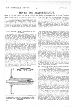
I97.—Care and Correct Adjustment of the Lacre Clutch.
The immunity of a motor vehicle from liability to breakdown is largely dependent upon the action of its clutch. A fierce clutch imposes severe stresses upon engine, gears, and, in fact, every part of the machine, and may even cause failures. On the other hand, a slipping clutch is a source of annoyance, and may result in a stoppage ; also slipping rapidly destroys the clutch fabric.
The clutch used on the Lacre vehicle is of the leather-covered-cone type engaging with the flywheel. The cone has a large diameter, and the frictional area tips obtained necessitates only a comparatively light spring to provide the necessary power-transmitting capacity. The position of this spring, and its small sire, are sources of wonderment to many mechanics when they dismantle a Lacre, clutch for the first time.
The spring is threaded over a round-headed with
drawal bolt about 8 ins, long, screwed Whit
worth. A keyway is milled three parts of the
way up this bolt, and the latter, with the spring threaded over it, is inserted into the hollow spigot end of the crankshaft, with the head of the bolt foremost. Both spring and bolt are retained in position by a drilled brass plug, which screws into the spigot end. One end of the withdrawal bolt passes through the hole, in the plug, and a key is fitted into the plug engaging with the keyway in the withdrawal bolt, thus preventing the latter from turning.
The clutch cone which is a steel pressing, is bolted on to an externally splined sleeve, fitted with gunmetal bushes, and a running fit on the crankshaft spigot end. Accommodated in the rear end of this sleeve is a ball-thrust race, and the projecting end of the bolt passes through this race. On to this bolt end is then screwed a large circular nut drilled for turning by means of a toinmy-bar, thus giving a means of adjustment for the spring pressure. There is a limit to the adjustment which can be given, as the head of the withdrawal bolt compresses the clutch spring back against the brass plug, but ample adjustment is provided before this stage is reached.
The friction surface is built up from three shaped sections of leather, copper-riveted to the face of the cone. Between the cone and the leather are three pieces of spring steel, 8 ins. by 3 ins., and 24 S.W.G. Each of these is held in place by two of the copper rivets holding the leather. On the inner face of the tone are threc small laminated, springs, each carried on a small steel block, held to the cone by two set
screws. The projecting ends of each spring are drilled, and through,each end is passed a setscrew, with a flat head 2-in. diameter. These heads pass through corresponding holes in the clutch cone and rest against the steel pressure plates under the clutch leather. Adjustment of these setscrews is obtained by two locking nuts on each. Qne nut is at the inner side of the spring, through which the screw passes, and the other at the outer side.
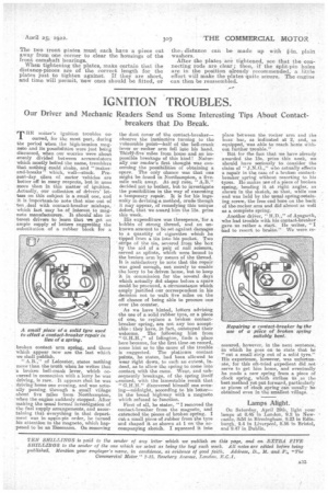
198.—Fitting Oil Baffle Plates on Reconditioned Thornycroft Vehicles.
For those engines which are not already supplied with oil baffle plates, the makers will provide a set complete with special studs' distance-pieces and nuts, and the following method of procedure in fitting them has been found to be very practicable where time is important:— Dismantle the engine in the chassis, taking off the the inlet and exhaust pipe, magneto, water pump and cylinders, if the water-pipe connection between the cylinders is handled carefully, it can be replaced without fitting a new rubber ring. Three side inspection plates should be taken off, leaving the offside rear plate, as it is awkward to remove owing to the position of the steering box. It is advantageous to take out the tappets and tappet guide holding-clown studs, as the four centre cylinder studs have to come out. These are sometimes very obstinate, and a large pair of "footprints" may have to be used.
In fitting the four special studs it is an advantage to have the split-pin holes in the lower part of the studs securing the plates parallel with the engine. The sides of the plates should be bent over before placing them into position. This saves the hole being slotted, as the edge grips the side of the casting and prevents the plate from moving. As supplied, the sides of the plates are vertical, and the amount to which they should he bent is about 30 degrees.
The two tront plates must each have a piece cut away from one corner to clear the housings of the front camshaft bearings. When tightening the plates, make certain that the distance-pieces are of the correct length for the plates just to tighten against. If they are short, and time will permit, new ones should be fitted, or the distance can be made up with, plain washers.
After the plates are tightened, see that the connecting rods are clear ; then, if the split-pin holes are in the position already recommended, a little effort will make the plates quite secure. The engine can then be reassembled.