MECHANICAL PRINCIPLES.
Page 14

Page 15

If you've noticed an error in this article please click here to report it so we can fix it.
In Loading anii Unloading Vehicles. Mainly About Unloading.
E HAVE NOW dealt separately with the VVmain mechanical :principles involved in all • schemes intended to facilitate or accelerate loading and unloading. These principles may be applied singly or together. Thus, for example, if -a we rope gear be used to enable the engine power to draw the load up a sloping way from the ground to the tail of a platform, we are using the principle of the lever and also the principle of the inclined plane. Similarly, in .each•vehicle which is unloaded by tilting, we are using both these principles. Thatof the laver is applied directly to the tilting body and that of the inclined planeis applied 'through the.
• medium of a screw to increase-the mechanical advantage obtained. •
In the notes on the subject of friction in the last artiele,inention was made of the angle of repose, that is to say, the greatest angle to which the supporting plane can be tilted without the thing suPported upon it beginning Id run down. Now the friction between bodies that are stationary in contact with one another
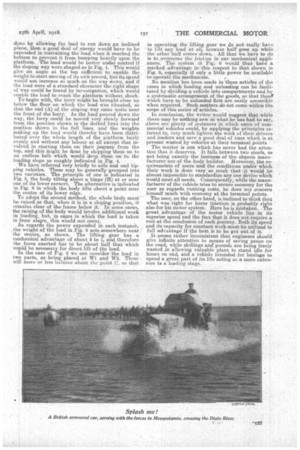
is' greater than the friction between them When relative motion has begun to take place. Consequently, it follows that if the ;nclined plane in Fig, t is at just such an angle that the weight (W) placed upon it will overchme friction and begin to move down, the friction will decrease so soon as the movement starts and, the resistance to motion ,grciw. ing less, the load will descend at a rapidly increasing speed. This means that if no work has to be done in giving the load a push off at the top, some work will almost certainly have to be done in preventing it from gathering speed and coming down with .a bump. If the sloping way instead of being an ordinary inclined plane, were shaped npon a curve more or less as in Fig. '2; the descending kind would -be under. bettercontrol, and if the load be such that it: is capable of being roiled, then the more gradual the inclined -plane, the more easily will the work of unloading be performed.
Similarly, if a vehicle were to be loaded from a. platform at a considerable elevation and this Were
done by allowing the load to run down an inclined plane, then a good deal of ,energy would have to be expended in restraining the load when it reached the bottom to prevent it from bumping heavily upon the platform. The load would be better under control if the sloping Way were shaped as in Fig. 4. This would give an angle at the top sufficient to exiable the weight to start moving of its own accord, but its speed would not increase so much on the way down, and if the load were of a standard character the right. shape of way could be found by investigation, which would enable the load to reach the platform without shock. Terbegin with, the lorry might be brought close up below the floor on which the load was situated, so that the end (A) of the sloping way came quite near the front of the lorry. As the load poured down the way, the lorry -could be moved very slowly forward from the-position shown in the dotted lines into the position shown in the full lines, and the weights making up the load would thereby-have been distributed over the whole length . of the platform fairly evenly and without any labour at all except that in-volved in starting them on their journey from the top, and this Might be done by shipping them on to an endless belt which would drop them on to the loading slope as roughly indicated in Fig. 4.
We have referred very briefly to side and end tipping vehicles. These may be 'generally grouped into two varieties. The principle of one is indicated in Fig. 5, the body tilting about a hinge (H) at or near one of its lower corners. The alternative is indicated in Fig. 6 in which the body tilts about a point near the centre of its lower edge.
To adopt the second method, the Whole ISody must be raised so that, when it is in a sloping position,, it remains clear of the-frame below it. In somecases, the raising of the body would involve additional work in loading, but, in eases in which the load is taken in from &stave, this would not occur. As regards the power expended in each instance, , the weight of the load in Fig. 5 acts somewhere near the centre, as shown. The lifting gear has a mechanical advantage of about 2 to 1, and therefore the force exerted has to be about half that which would be necessary for direct lift of the load. In the case of Fig. 6 we can consider the load in two parts, as being placed at W1 and W2. These will more or less balance about the point C. so that in operating. the lifting gear we do not really have, to lift any load at all, because half goes. up while the other half comes. down.. All that we have to do is to overcome the friction in our mechanical appliances. The system in Fig.. 6 would thus have a marked advantage in: this respect to that shown in Fig. 5, especially if only a little, power be available to operaee the mechanism.,
No mention has been made in these articles of the cases in which loading and unloading can be facilitated by dividing a vehicle into compartments and by a systematic arrangement of the goods, so that those which have to be unloaded first are easily accessible when required. Such matters do not come within the scope of this series of articles.
In conclusion, the writer would suggest that while there maybe nothing new in what he has had to say, sthere are plenty of instances in which users of commercial vehicles could, by applying the principles referred to, very much lighten the work of their drivers and loaders and save a good deal of time which is at present wasted by vehicles at their terminal points.
The matter is oat which has never had the attention that it deserves. It falls between two stools, as not being exactly the business of the chassis manufacturer nor of the body builder. Moreover, the requirements of users and the conditions under which their work is done vary .so much that it would ise almost impossible to standardize any one device which would meet all needs. Consequently, while the manufacturer of the vehicle tries to secure economy for the user as regards running costs, he does not concern himself much with. economy at the terminal' points.
The user, on the other hand, is inclined to think that what was right for horse traction is probably. right also for his motor system. Here he is mistaken. The great advantage of the motor vehicle lies in its superior speed and the fact that it does not require a rest at the conclusion of each journey. Both its speed and its capacity for constant work-must be utilized to full advantage if the best is to be got out of it.
It seems rather inconsistent that engineers should. give infinite attention to means of saving pence on the road., while shillings and' pounds are being freely wasted an Allowing valuable plant to stand idle for hours on end, and a vehicle intended for haulage to spend a great part of its life acting as a mere eatensoon to a loading stage.


