


n Vehicle n Yaxrnm ( o)Aucoi r corig
Page 91
If you've noticed an error in this article please click here to report it so we can fix it.
A TURBOCHARGER consists, basically, of a turbine, powered by a vehicle's exhaust gases, which is directly coupled by a shaft to a centrifugal compressor. This compressor compresses the inlet air, forcing it into the cylinders at a far greater density than is possible with naturally aspirated engine. This harnesses a source of energy which would otherwise be wasted, that is the energy of the exhaust gases flowing down the exhaust pipe. A diagram of a turbocharged engine, and how the gases flow, appears in Figure 1.
The turbine and compressor wheels are each contained in their own cast-iron casing and are connected to each other by a steel shaft. A sectioned view of a turbocharger fitted to a Cummins engine appears in Figure 2.
Turbochargers run at very high speeds — one manufacturer quotes figures of 80,000 to 130,000 revolutions per minute. At the lower of these two speeds the tips of a 76.2mm (3in) diameter turbine will be travelling at 700mph while at 130,000 revolutions per minute a speed of 1,160mph will be reached.
With speeds of this magnitude, sound construction and perfect balance of the rotating parts is essential. Because of the high rotational speeds it is also necessary to keep the mass (weight) of the wheels as low as possible. For this reason, aluminium alloy is used for the compressor wheel but this metal cannot be used for the exhaust turbine because of the high temperature present in this side of the machine. The temperature here is in the region of 700°C (1,300°F) so a special alloy of nickel and chrome is employed.
The drive shaft is usually supported in either two separate fully floating bearings or a single floating bearing whose contact area is reduced in the middle by an annular groove, making its area of contact equal to two short bearings. As the bearing is free to rotate in its housing the bearing turns in the same direction as the shaft but at a substantially slower speed. This reduces friction and generates less heat.
Proper lubrication of the shaft and its bearings is of vital importance. Engine oil is usually fed under pressure to the turbocharger and the oil acts, not only as a lubricant but also as a coolant. The oil drains back to the engine sump by gravity after leaving the unit. In some cases an additional filter is incorporated in the oil supply line to the turbocharger. Any intake of foreign materials into a turbocharger will have disastrous results so an efficient air cleaner is essential.
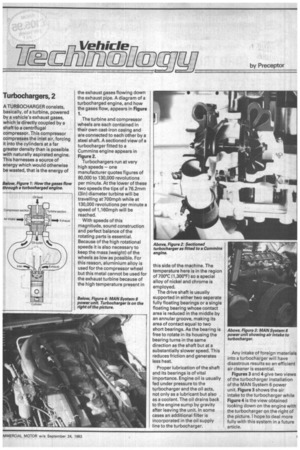
Figures 3 and 4 give two views of the turbocharger installation of the MAN System 6 power unit. Figure 3 shows the air intake to the turbocharger while Figure 4 is the view obtained looking down on the engine with the turbocharger on the right of the picture. I hope to deal more fully with this system in a future article.