


HINTS ON MAINTENANCE.
Page 28
Page 29
If you've noticed an error in this article please click here to report it so we can fix it.
How to Get the Best Out of a Vehicle, to Secure Reliability and to Avoid Trouble.
CONTRIBUTIONS are invited for this page from fleet managers, drivers, garage foremen, and mechanics, works staff and draughtsmen, and will be paid for on a generous scale. Every system, make, and type of commercial motor vehicle will be dealt with, and the matter should be written with a view to the disclosure of workshop and garage practice in the maintenance of a vehicle—practices which„ whilst they may be quite normal, are peculiar to the particular vehicle and may not be generally known to those responsible for its running. • Expedients and suggestions for overcoming .roadside and other troubles are covered in the following •page, dealing with letters from our driver: and mechanic readers. Communications should be addressed to " The Editor, The Commercial Motor, 7-15, RoSehery Avenue, London, E.C.1."
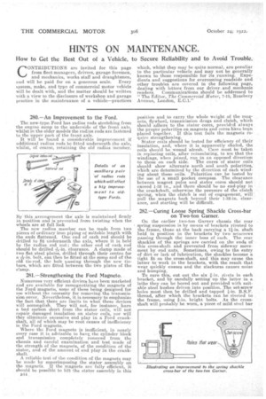
280.—An Improvement to the Ford.
The new-type Ford has radius rods stretching from the engine sump to the underside of the front axle, whilst in the older models the radius rods are fastened to the upper part of the front axle.
It will be found a considerable improvement if additional radius rods be fitted underneath .the axle, whilst, of course, retaining the old radius member.
By this arrangement the axle is maintained firmly in position and is prevented from twisting when the wheels are at full lock The new radius member can be made from two pieces of ordinary iron piping of suitable length with the ends flattened. One end of each rod should be drilled to fit underneath the axle, where it is held by the fading rod nut ; the other end of each rod should be drilled A-in. clearance. A clamp made of two fiat steel plates, drilled through their centre for *-in. bolt, can then be fitted at the sump end of the old tie-rod, the bolt passing through the new tiebars, which are fitted between the two plates of the clamp.
281.--Strengthening the Ford Magneto.
Numerous very efficient devices have been marketed and are available for remagnetizing the magnets of the Ford magneto, some of these being designed for use without the necessity for removing the transmission cover. Nevertheless,. it is necessary to emphasize the fact.that there are limits to what these devices will accomplish. They will not, for instance, burn a bad carbon short from the stator coils, will not repair damaged insulation on stator coils, nor will they eliminate excessive end play in a Ford crankshaft, all of which may be root causes of inefficiency in the Ford magneto. • Where the Ford magneto i W s inefficient, in nearly
every case it is advisable to have the cylinder block and transmission completedy removed from the chassis and careful examination and test made of the strength of the magnets, of the condition of the stator, and of the amount of end play in the crankshaft.
A reliable test of the condition of the magnets may he made by superimposing the stator ,assembly on the magnets. If the magnets are fully efficient, it should be possible to lift the stator assembly in this Jilt . position and to carry the whole weight of the magnets, flywheel, transmission drugs and clutch, which should adhere to the stator -cores, provided always the proper polarities on magnets and cores have been placed together. If this test fails the magnets require strengthening. Stator coils should be tested for efficiency of their insulation, and, where it is apparently chafed, the coils should be wound afresh. Care must be taken in replacing coils, after reinsulating, to see that the windings, when joined, run in an opposed direction
to those on each side. The cores of stator coils should show alternate north and south polarities,which are determined by the direetion of each winding about these coils. Polarities can be tested by the use of a small pocket compass. The clearance between magnet poles and stator cores should not exceed 1-32 in., and there should be no end-play in the crankshaft, otherwise the pressure of the clutch spring, when the clutch is out of engagement,. will pull the magnets back beyond their 1-32-in clearance, and starting will be difficult.
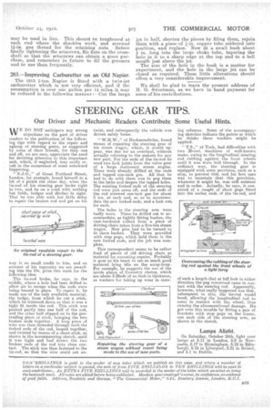
281—Curing Loose Spring Shackle Cross-bar on Two-ton Garner.
On the earlier two-ton Garner chassis the rear spring suspension is by mians.of brackets riveted to the frame, those at the back carrying a 11-in. shaft held in position in the brackets by two 'setscrews passing through the inner boss of each The rear shackles of the springs are carried on the ends of this cross-shaft and prevented from sideway movement by end nuts. Sometimes, owing to the entry of dirt or lack of lubrication, the shackles become a tight fit on the cross-shaft, and this may cause the latter to work in the brackets, with the result that wear quickly ensues and the slackness causes noise and bumping.
To cure this, cut out the six 1-in. rivets in each bracket, and by carefully setting up the latter in a lathe they can be bored out and provided with suitable steel bushes driven into position. The set-screw holes must then be drilled and tapped B.S.F. thread, after which the brackets can be riveted to the frame, using k-in. bright bolts. As the cross shaft will probably be worn, a piece of mild steel bar
may be used in lieu. This should be toughened at each end where the shackles work, and screwed 11-in, gas thread for the retaining nuts. Before finally tightening the setscrews, file flatson the crossshaft so that the setscrews can obtain a good purchase, and remember in future to fill the greasers and to use them frequently.
283.—Improving Carburetter on an Old Napier.
The 1913 1-ton Napier is fitted with a twin-jet carburetter which is not very efficient, and if the consumption is over one gallon per 14 miles it may be reduced in the following manner :—Cut the large jet in half, shorten the, pieces by filing them, rejoin them with a piece of 1-in. copper tube soldered into position, and replace. Now lit a small bush about in. tong into the large choke tube, tapering the hole in it to a sharp edge at the top and to a bell mouth just above the jet. The size of the hole in the bush is a matter for experiment, and the hole in the large jet can be closed as required. These little alterations should effect a, very considerable improvement.
We 8hal.1 be glad to learn the present address of H. G. Sweetman, as we have in hand payment for some of his contributions.