


Patents Completed.
Page 22
If you've noticed an error in this article please click here to report it so we can fix it.
An Improved Scavenge.
F. H. Tanner, No. 22,155, dated 9th October, 1911.—This invention relates to two-cycle engines in which scavenging air is used, and it may be applied to engines
of the type described in Patent No. 23,104, of 1906. The inlet and exhaust ports for scavenging air are usually arranged to make the exhaust port open before the inlet port. In order to maintain the necessary strength of the cylinder on that section, the size of the ports is restricted; in practice the ports do not subtend an angle of more than 100 degrees. According to the present invention two inlet ports are provided for the air, set at an angle of about 110 degrees, with a single outlet port on the opposite aide. By this arrangement the cylinder is pierced by three openings which leave three sections of metal of sufficient strength to withstand the force of the 13Xplosion on the cylinder head. The deflector on the piston must be extended round, as shown, to be available for both the inlet ports.
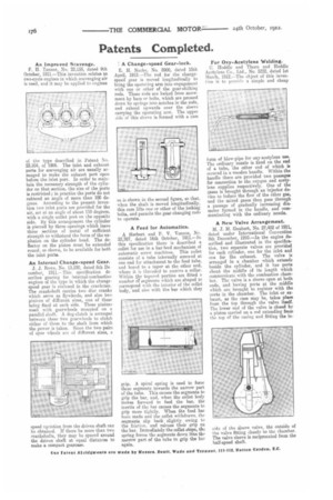
An Internal Change-speed Gear.
J. J. Rowe, No. 13,520, dated 6th De. eember, 1911.—This specification describes gearing for internal-combustion engines of the type in which the changespeed gear is enclosed in the crankcase. The crankshaft carries two disc cranks which serve as flywheels, and also two pinions of different sizes, one of these being fixed at each side. These pinion; mesh with gearwheels mounted on a parallel shaft. A dog-clutch is arranged between these two gearwheels to clutch either of them to the shaft from which the power is taken. Since the two pairs of spur wheels are of different sizes, a speed variation from the driven shaft can be obtained. If there be more than two crankshafts, they may be spaced around the driven shaft at equal distances to make a compact gearca,se.
A Change-speed Gear-lock.
E. H. Nacke, No. 8900, dated 15th April, 1912.—The rod for the changespeed gear is moved longitudinally to bring the operating arm into engagement with one or other of the gear-shifting rods. These rods are locked from movement by bars or bolts, which are pressed down by springs into notches in the rods, and extend upwards over the sleeve carrying the operating arm. The upper side of this sleeve is formed with a earn as is shown in the second figure, so that, when the shaft is moved longitudinally, this cam lifts one or other of the locking bolts, and permits the gear-changing rods to operate.
A Feed for Automatics.
A Herbert and P. V. Vernon, No. 22,767, dated 16th October, 1911.—In this specification there is described a collet for use in a bar-feed mechanism of automatic screw machines. This collet consists of a tube internally screwed at one end for attachment to the feed tube, and bored to a taper at the other end, where it is threaded to receive a collar. Within the tapered portion are fitted a number oi-segments which are shaped to correspond with the interior of the collet body, and also with the bar which they grip. A spiral spring is used to force these segments towards the narrow part of the tube. This causes the segments to grip the bar, and, when the collet body moves forward to feed the bar, the inertia of the har causes the segments to grip more tightly. When the feed has been made and the collet withdraws, the segments slip back slightly owing to the friction, and release their grip on the bar. Immediately the collet stops, the spring forces the segments down into the narrow part of the tube to grip the bar again.
For Oxy-Acetylene Welding.
C. Hoddle and Thorn and Hoddle Acetylene Cu., Ltd., No. 5222, dated 1st March, 1912.—The object of this invention is to provide a simple and cheap form of blew-pipe for oxy-acetylene use. The ordinary nozzle is fixed on the end of a tube, the other end of which is secured in a wooden handle. Within the handle there are provided two passages for connection to the oxygen and acetylene supplies respectively. One of the gases is brought through an injector device to induce the flow of the other gas, and the mixed gases then pass through a passage of gradually increasing diameter formed in the handle, and communicating with the ordinary nozzle.
A New Valve Arrangement.
M. J. M. Gaubert, No. 27,452 of 1911, dated under International Convention 8th December, 1910.—In the engine described and illustrated in the specification, two separate valves are provided for each cylinder, one for the inlet and one for the exhaust. The valve is arranged in a chamber which extends beside the cylinder, and it has ports about the middle of its length which communicate with the combustion chamber. The valve is a sleeve open at both ends, and having ports at the middle which are brought to register with the ports in the chamber. The inlet or exhaust, as the case may be, takes place from the top through the valve itself. The lower end of the valve is closed by a piston carried on a rod extending from the top of the casing and fitting the in side of the sleeve valve, the outside of the valve fitting closely to the chamber. The valve sleeve is reciprocated from the half-speed shaft.