


An Hydraulically Operated Gearbox
Page 36
If you've noticed an error in this article please click here to report it so we can fix it.
AGEARBOX in which the ratio is selected by hydraulic means is shown in patent No. 564,317 by G. .B. (Nottingham), Ltd., 23, King Street, Nottingham, and others. Although illustrated as applied to a motorcycle, the scheme is intended to apply equally to all types of vehicle.
In the construction shown, which is rather unorthodox, the crankshaft forms one shaft of the gearbox, and is fitted with three gears (1, 2 and 3). Each is in constant mesh with its corresponding gear on the output shaft (4). Taking the low-speed train as an example the teeth are formed on an annulus (5), which is freely journalled on the shaft. Inside the gear is a friction clutch consisting of a pair of expansible shoes, very much likea conventional brake mechanism. The shoes can be expanded by a pair of hydraulic pistons, shown ,end-on at 6; when under pressure these pistons cause the gear to be locked to its shaft, The pressure fluid (lubricating' .oil) is pumped into the hollow shaft and is directed to any desired expander by means of asliding valve (7), , which. is Operated by a rack-and-pinion (8), .
WHEEL-MOUNTING FOR LOW-' LOADING VEHICLES
I NTENDED .chiefly for. -low-floored trailers, an improved method of mounting the wheels-forms the Subject of patent No. 564;100, from .R, Gonicin, 23,: Woburn Hill, ,Stoneycrolt, Liver: poOI 13: With the object of reducing the ground clearance to the minimum, the axles are dispensed with and the wheels fixed to the sides of the chassis. The drawing Outlinesthe scheme; in which cross-members (1) give lateral rigidity and form the,point Of 'attachment of the Wheel frames. The latter consist of an inverted "1-structure (2), which is arched to embrace both sides of thewheel.
REMOTE CONTROL FOR FOG-LAMP
-A MEANS by which fog-lamps, spot1-1 lights and similar special lamps, can be remotely controlled, forms the subject of patent No. 564,426, from S. Knight, The Hill, Barrow-on-Trent, Derbyshire. This inventor proposes to mount the lamp on a universal bracket (1), which can be rotated by a worm (2) and rocked by another worm (3). The worms are connected by a species
of speedometer cable to a doubleknobbed control .(4) on, say, the dashboard, so that the driver can easily move his distant lamp into any position.
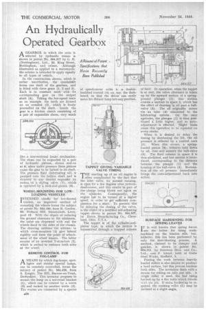
TAPPET GIVING VARIABLE VALVE TIMING
THE starting up of an oil engine is often complicated by the fact that the inlet valve, for normal running, is open for a few degrees alter bottomdead-centre, and this results in part of the -charge being blown out ag'airi on the upstroke. Consequently, the engine hat to be turned at a higher speed, in order to get sufficient compression for a. start, To prevent this by delaying the closing of the valve, is the object.of a modified self-adjusting tappet shown in patent No. 564,507, by Eaton Manufacturing Co., Cleveland, Ohio, U.S.A.
The tappet is of the cylinder-andpistontype, in which the motion is transmitted through a trapped column of fluid. In operation, when the tappet is at rest, the valve clearance is taken up by the upward motion Of a springpressed plunger (I); this motion creates a suction in space 2, which has the effect of drawing in oil past a ballvalve (3). The oil originally enters via an inlet (4) connected to the lubricating system. On the next upstroke, the plunger (1) is thus positioned 6. little higher, and so autoadjustment is effected. Slight leaks cause this operation to be repeated on every stroke.
When it is desired to delay the timing by shortening the lift, the oil pressure is relieved by a control cock (5). When this occurs, a spring. loaded piston r(6), hitherto held down by oil, rises and unseat t the ball-valve (3). The fluid column in space 2 is thus abolished, and lost motion is introduced, corresponding to the distance between the plunger (1) and the housing of the ball-valve (3). Restoration of the oil pressure immediately brings the .auto-adjustment back into action.
SURFACE HARDENING. FOR SPRING LEAVES
is well known that spring leaves
are thebetter for being work7 hardened -on the tension side, but, hitherto, this has been performed by only the shot-blasting process. A method, claimed to be cheaper and quicker, is shown in patent No. .564,311, by lbbotson Bros. and Co., Ltd., and F. Lloyd, both of Globe Steel Works, Sheffield, 3.
Passing the work between .heavily loaded rollers is also known to produce a hard surface, but this process hardens both sides. The invention deals with a means for rolling. on Onlyone side, A single roller is used, the leaf being backed up by a fiat table which travels with the job. If extra hardening he required, the working roller (1) may be inclined at a slight angle.