 1
1 2
2 3
3 4
4 5
5 6
6 7
7 8
8 9
9 10
10 11
11 12
12 13
13 14
14 15
15 16
16 17
17 18
18 19
19 20
20 21
21 22
22 23
23 24
24 25
25 26
26 27
27 28
28 29
29 30
30 31
31 32
32 33
33 34
34 35
35 36
36 37
37 38
38 39
39 40
40 41
41 42
42 43
43 44
44 45
45 46
46 47
47 48
48 49
49 50
50 51
51 52
52 53
53 54
54 55
55 56
56 57
57 58
58 59
59 60
60 61
61 62
62 63
63 64
64 65
65 66
66 67
67 68
68 69
69 70
70 71
71 72
72 73
73 74
74 75
75 76
76 77
77 78
78 79
79 80
80 81
81 82
82 83
83 84
84 85
85 86
86 87
87 88
88 89
89 90
90 91
91 92
92 93
93 94
94 95
95 96
96 97
97 98
98 99
99 100
100 101
101 102
102 103
103 104
104 105
105 106
106 107
107 108
108 109
109 110
110 111
111 112
112 113
113 114
114 115
115 116
116 117
117 118
118 119
119 120
120 121
121 122
122 123
123 124
124 125
125 126
126 127
127 128
128 129
129 130
130 131
131 132
132 133
133 134
134 135
135 136
136 A 241 bhp VO from AEC with built-in stretch'
Page 78
Page 79
Page 80
If you've noticed an error in this article please click here to report it so we can fix it.
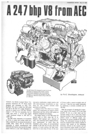
TODAY, the British Leyland Motor Corporation announces the V8 diesel engine designed and developed at AEC Ltd., Southall. The unit is called the 800 series V8 and is the first of a range designed to operate at outputs up to 350 bhp. Initially, output is 247 bhp net (excluding fan) at 2,600 rpm—from a 12.154 litre engine —and maximum torque is 580 lb.ft. at 1,400 rpm.
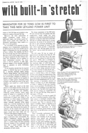
The 800 series represents an investment of £2.5m in plant and tooling which provides a capacity for an annual production of 13,000 units. There will be world-wide marketing to vehicle manufacturers and industrial and marine users but the first application will be to a new AEC Mandator 32 tons-gross combination weight tractive unit with semi-automatic transmission as stan dard sixand 10-speed constant mesh gearboxes are options.
A feature of the V8 is that it is a "metric engine" (all components are made to metric dimensions) and this will be LMC policy on all future, completely new designs.
The design history of the 800 series V8 started early in 1962, when Mr. D. K. Roberts, chief engineer and a director of AEC, was reviewing future engine performance requirements. In those days the maximum gross rating of non-specialized vehicles in the UK was 24 tons, and in the majority of world markets the legal maximum was no more than 30 tons. In the case
of 24-ton outfits a power-to-weight ratio of well over 7 bhp /ton was readily obtainable by employing a currently available unit of 180 bhp.
With the prospect of catering for a maximum rating in this country of 32 tons (and possible 38 tons at a later date) and for overseas ratings of 42 or more tons, future planning exercises were concentrated on the relative merits of different engine configurations for powers suitable for the higher ratings. The anticipated increase in the demand for maximum-load vehicles capable of sustained high speeds on the expanding motorway network in this country and on trans-Continental routes would, it was envisaged, create a need for power units with an output of 240 /250 bhp and probably in due course for engines of around 300 bhp.
Moreover, the strict enforcement of weight regulations would favour a lightweight engine, one having a good lowspeed torque output that could give an acceptable performance when mated to a fiveor six-ratio gearbox.
An assessment of the potential of turbocharging was a fundamental consideration in deliberations on the most suitable type of engine configuration for the new generation of heavy vehicles. The reliability and life of the turbocharger has now been improved to the extent that it will be approved as an item of original equipment but Mr. Roberts forecasts that acceptance will be confined to more sophisticated countries. For many years it will be necessary to offer high
• powered engines of the naturally aspirated type to operators in newly developing countries.
It was therefore decided that the required output of 240/250 bhp had to be provided by a naturally aspirated engine having "built-in design features" that would enable it to be uprated by detailed refinements and by turbocharging. Designed to operate at a medium speed, it should also be capable of running at higher speeds; endurance testing at higher rpm would give proof of the unit's reliability and would be a useful research exercise.
Piston speed was viewed as the main criterion in the design exercise, on the score that it was the single most important factor with regard to durability and reliability. Following normal practice, piston speed would be limited to a maximum of 2,100 ft /min. At a given piston speed, bhp is proportional to piston area (which is the parameter on which design considerations were mainly based). Producing a higheroutput naturally aspirated in-line engine would have involved employing six larger cylinders, reducing the stroke and running at a higher rpm. Alternatively the number of cylinders (of the original bore and stroke) could have been increased to eight but the engine would have been bulky and not economic with regard to weight and cost.
A large-bore (short-stroke) six-cylinder engine would have been unacceptable, Mr. Roberts emphasized, because its length would have created installation difficulties; and if a critical length had been exceeded torsional vibration of the crankshaft would have been a major bugbear. An eightcylinder engine would have been unacceptable on both counts.
The design parameters of the 800 series V8 were derived from the premise that this configuration would enable two extra cylinders to be used (a numerical increase of one-third) having the same bore as the AEC 180 bhp six-cylinder engine then in current production, the stroke to be reduced by 25 per cent to give structural advantages and the rpm to be increased by about 30 per cent, which would provide a comparable piston speed. The 180 bhp engine was thus the "datum" unit on which the exercise was based.
The 800 series V8 has an output of approximately one-third more than the 180 bhp datum unit, the bore size is the same and the stroke is reduced by rather less than one quarter. While rpm is increased by some 20 per cent, piston speed is well below the maximum limit of 2,100 ft/min. The engine operates at about the same b.m.e.p. of 115 psi. and compression ratio of 16 to 1 and its built-in design potential provides for an output increase of some 40 per cent.
The cubic capacity of 12.154 litres (741.7 cu.in.) is derived from a bore of 130mm (5.12in.) and a stroke of 114mm (4.5 in.). The ratings quoted at the beginning are obtained at a temperature and pressure given in the British Standard specification AU 141:1967. This stipulates a barometric pressure of 760mm, (29.92in.) an air inlet temperature of 20deg C (68deg F) and zero humidity (water vapour pressure). The laboratory test is made with all auxiliaries in use apart from the radiator fan. The DIN, SAE (gross) and SAE (metric) ratings are respectively 252 bhp, 265 bhp and 269 bhp. Idling speed of the engine is 470 rpm.
It is interesting to see the low speed (54 per cent of maximum speed) at which maximum torque is developed compared with other VS short-stroke (four-stroke) engines in common use. This is a measure of the engine's flexibility, which is regarded as an all-important attribute; and Mr. Roberts emphasized the importance of torque back-up (maximum torque /torque at peak rpm) which on the 800 series is no less than 17 per cent.
These favourable performance characteristics are attributed to careful development and matching of the air intake, injection spray pattern and combustion chamber characteristics. And Mr. Roberts pointed out that good matching and inter cylinder uniformity are no more difficult to obtain in the case of a short-stroke unit
(with a bit of luck) than the matching exercise in the development of the long
stroke engine.
Although the surface /volume ratio of a long-stroke engine of equivalent capacity would be more favourable than the ratio provided by the short-stroke unit, the difference is marginal because the shortstroke engine has a larger bore. In the development stage, the stroke of a modified 180 bhp datum six-cylinder engine with the same bore as the proposed V8 was reduced to 4.5in. to match the V8's stroke, and the unit produced more power and a higher torque than the standard engine. It also operated at a lower fuel consumption, corresponding to the consumption of the 800 series V8 of 0.369 lb/bhp /hr.
The design of the new unit was also influenced by "gearbox availability" prospects. It was correctly anticipated that pending the availability of higher-torque transmissions it would have to be mated with a gearbox having a maximum torque capacity of around 600 lb ft. Having a weight of 2,050 lb, the unit provides a power-to-weight ratio of 8.25 lb /bhp. This is nearly 20 per cent better than the ratio of the datum engine, and eventual uprating will give a more favourable ratio.
A short-stroke offers important constructional and weight advantages in that it enables the distance between the crankshaft centre line and the top of the block to be considerably reduced. A reduction in stroke of lin. provides for reductions in piston height and connecting-rod length of lin. and 1.5in. respectively, the overall gain being 3.5in. Other constructional advantages of a short-stroke unit include provision of a large crank-journal/pin overlap without excessively large journal and pin diameters, which enables a very robust but relatively light shaft to be used giving acceptable rubbing velocities. The journals of the 800 series crankshaft have a diameter of 3.747in. while the crankpin diameter is 3.499in., overlap being about 1.37in.
Because of its inherent stiffness, the crankshaft can be run up to the rated speed without a torsional vibration damper. Mr. Roberts stated that viscous dampers are subject to damage and rubber dampers are liable to overheating, particularly if the engine is operated continuously at a high speed.
Lubrication of the pistons represents a particular problem in the design of a short-stroke V8. As indicated, it is approp riate to use a relatively shallow piston with a short skirt and this creates oil-control difficulties, notably with regard to inter cylinder uniformity. The problem has been tackled in the case of the 800 series by careful attention to piston design and pis ton-ring layout. The aluminium pistons have a depth of 5.625in. and the barrelled top compression ring is carried in an Alfinbonded cast-iron insert. This ring is chromium-plated, while the second compression ring is internally stepped.
Also mounted above the gudgeon pin (which has a diameter of 2in.), the oilcontrol (scraper) ring is of the conformable type, the radial pressure that it exerts being entirely a function of the pressure of a backing coil spring. Provision is made in the short skirt for an additional scraper ring if it should be required following an overhaul.
Bore distortion by mechanical or thermal stresses has been minimized by strategic placement of eight 0.55in. (14mm) cylinder-head holding-down studs round each bore, and by providing ample water passages shaped to give directional flow in conjunction with the now well-known AEC longitudinal-flow cooling system. This gives a maximum temperature rise across the engine of 7 deg C.
Assisted by a centrifugal pump the coolant flows from the front of the lefthand block through a transfer pipe to the rear of the righthand block, from there to the righthand cylinder head through a second transfer pipe and then forward to the front of the engine through the lefthand head. Rigid construction is aided by the use of dry liners which are of centrifugally cast alloy iron. The thermostat is of the bellows-type which is preferred to the wax type because it "fails open".
The details
Filling in the details, the pistons have an open toroidal-cavity straight-sided chamber in the crown and fuel is sprayed obliquely into the chamber by a five-hole nozzle. Two valves having steilited seats and dual springs are fitted to each cylinder and intake air swirl is controlled by a masked inlet valve.
The connecting rods are I-section alloy-steel stampings and can be withdrawn through the cylinder bores, the small ends have steel-backed lead-bronze bushes and the big ends are fitted with aluminium-tin shell bearings. Connecting-rod betweencentre length is 9.56in. while the diameter of the big-end bolts is 0.551in. The projected area (gross) of the big-end bearing is 31.4 sq.in.
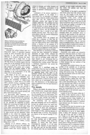
The nitrided crankshaft is supported by five main bearings and is fully counterbalanced, the crankpins being bored for lightness. To ensure that each 'piston/ connecting-rod assembly is of the same weight (in the interests of good balance) the little ends and the big ends incorporate external pads that are machined before assembly to give weight uniformity within fine limits. All pistons and rods are interchangeable.
End location of the shaft is provided by steel thrust strips lined with reticular aluminium tin. The lengths of the front, rear, centre and intermediate main bearings are respectively 1.72in., 2.2in., 1.875in. and 1.878in., the projected area of the bearings (gross) being 36.43 sq.in. A lip-type oil seal and an oil-thrower disc are fitted to the front of the shaft and sealing is provided at the rear by a nitrile rubber V-ring seal.
Rigidity of the fine-grain cast-iron cylinder block is enhanced by robust transverse webs and by wide joint faces. The block is extended below the crankshaft centre to provide for rigid location of the main bearing caps. Each cap is secured vertically by two 0.705in. diameter bolts and horizontally by two 0.393in. diameter set screws. The sump is of aluminium alloy (a cast-iron sump is available) having a deeper section at the front in which is located the oil pump. A detachable aluminium-alloy casting is used for the flywheel housing.
Valve-system interest
Renewable valve guides and pressed-in alloy-iron valve-seat inserts are fitted to the cylinder heads which are interchangeable. The injectors are located in copper sheaths to assist cooling while 0-ring seals are fitted to the inlet-valve guides. An expansion joint is fitted between the two sections of the exhaust manifold.
Of special valve-system interest, the cam profiles of the camshaft are of polydyne form which give "no-steps' acceleration and obviate resonance, as well as virtually eliminating valve-spring surge. The diameters of the inlet and exhaust valves are both 2.09in. (53mm) diameter.
Supported on five bearings, the camshaft is driven through a helical gear train. The crankshaft gear wheel drives the oil pump and a main intermediate gear. This meshes with the camshaft gear which in turn drives the fuel injection pump and compressor through a further gearwheel. Two additional gears are incorporated in the train to drive auxiliaries such as the hydraulic pump of a power-steering system.
Located on top of the engine within the V the Simms in-line injection pump is fitted with an all-speed mechanical governor, fuel at constant pressure being supplied by a piston /diaphragm-type of lift pump. The oil filter of the lubrication system is a full-flow paper-element type, the capacity of the system being 5.5gal.
The radiator fan may be mounted on the front of the crankshaft (and driven at crankshaft speed) or mounted above the crankshaft and belt-driven at up to If times engine speed. A Butec 24V alternator is mounted on the left of the unit and is driven by two V-belts at 2.6 times engine speed. It has a standard output of 30 amp, while a larger unit is available having an output of 60 amp. A Butec 24V axial-engagement starter motor is flange-mounted on the left of the bell-housing and if a compressor is fitted it is located in the V and driven in tandem with the injection pump. The compressor is a twin-cylinder air-cooled type.