


Self-limiting Brake Mechanism
Page 48
If you've noticed an error in this article please click here to report it so we can fix it.
PATENT No. 913,838 shows a valve for a hydraulic brake operating system that automatically cuts off the supply of fluid to the rear brakes when the rate of deceleration reaches a predetermined value. (Automotive Products Co. Ltd., Tachbrook Road, Leamington Spa.)
The device illustrated is incorporated in the pipeline to the rear brakes. It consists of a cylindrical casing containing a loose-fitting cylindrical plug (1). The plug is pivoted on a pin (2) so that it can rock slightly. Brake fluid can normally pass through the clearance space, entering at the lower port (3).
Assuming the device to be on a vehicle travelling to the left, a deceleration force would cause the plug to rock to the left. Its action would then be to obstruct the outlet by means of a sealing pad (4), while the fluid flow would tend to assist the action.
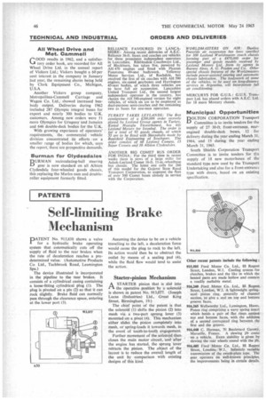
Starter-pinion Mechanism
1-1 A STARTER pinion that is slid into
the operative position by a solenoid is shown in patent No. 913,077. (Joseph Lucas (Industries) Ltd., Great King Street, Birmingham, 19.) The chief point of the patent is that the solenoid (I) shifts the pinion (2) into mesh via a two-part sprung lever (3) mounted on a pivot (4). This mechanism either slides the pinion completely into mesh, or spring-loads it towards mesh, in the event of tooth-to-tooth engagement.
Further movement of the solenoid then closes the main motor circuit, and after the engine has started, the sprung lever retracts the pinion. The object of the layout is to reduce the overall length of the unit by comparison with existing designs of this kind.