


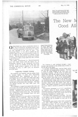
The New rris-Commercial Good All
Page 42
Page 43
Page 44
If you've noticed an error in this article please click here to report it so we can fix it.
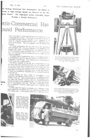
-und Performance OPERATORS .have shown considerable interest in the Morris-Commercial oil-engined chassis since it was first announced in this journal on April 9 and fully described in the April 16 issue. "The Commercial Motor" is now able to publish the first road-test report of the new forward-control model, the cab of which has been designed to enhance driving comfort. This test proved the new chassis to be capable of operating at a high average speed and with a marked degree of economy.
The engine, manufactured by Morris-Commercial Cars, Ltd., under licence from the Saurer Co., of Switzerland, operates on the well-proved four-stroke principle. It has six cylinders of 85 mm. bore and 125 mm. stroke, giving a capacity of 41 litres and developing 75 b.h.p .at 2,400 r p.m., its maximum governed speed.
Light-alloy Cylinder Casting The crankcase, cast integrally with the cylinder block to increase rigidity, is made from heat-treated aluminium-silicon alloy. Detachable wet liners of centrifugally cast iron ate fitted, and ample water space is provided. Seven main bearings are formed in the crankcase to support the crankshaft; the caps supporting the shaft are--aluminium-alloy stampings. The main and big-end bearings have steel shells lined with copper-lead.
The crankshaft is forged from special alloy steel, and all its main and crankpin journals are heat-treated and hardened to prolong the life of the crankshaft and its bearings. Machined from cast-iron alloy, the flywheel has kreplaceable toothed starter ring. The connecting rods are H-section steel stampings fitted with plain phosphor-bronze bushes.
Specially designed cavity-type pistons of heat-treated aluminium alloy are employed. They have fully floating gudgeon pins and lour compression and two slotted scraper rings. Mounted high on the cylinder block in five plain bearings, the camshaft is located at the front end by a ball bearing and is driven from the crankshaft by a triplex roller chain. This chain drive also links up the C.A.V. injection pump and incorporates an automatic tensioner. Jets of oil are sprayed on to the chain to prolong its life and ensure quiet operation: The crankcase is well ventilated through a largediameter pipe attached to the oil-filter-body bracket on the left side of the engine.
A one-piece chromium-alloy cast-iron head carries the valve gear and poppet-pattern injectors. Provision is made for ample cooling of the valve ports and fuel-injector housings All the valves are made from special alloy steel and the rockers operate through the medium of push-rods. As the inlet valves are larger than the exhaust valves they are not interchangeable.
Decompressor screws are fitted to the cylinder head. An aluminium-alloy casing, open at the top, surrounds the valve-rocker gear and incorporates the air-induction manifold, which carries the venturi valve and air cleaner. This casing is enclosed by a quickly detachable top cover, which is secured in position by three hand screws.
Fuel-injection equipment is of C.A.V. manufacture, the injectors being of Saurer patented design. A pneumatic governor is incorporated in the fuel-injection pump and connected to the venturi throat valve of the air-induction manifold by a flexible pipe.
Four-point rubber suspension is provided. The front of the engine is carried by brackets on the timing-case cover and the rear on brackets on each side of •the clutch housing.
The single-dry-plate clutch is fitted with a spring-drive centre plate, which provides ease of operation and smoothness of action. Of unit construction with the engine and clutch, the four-speed gearbox is made of cast iron. All the gearwheels have wide teeth and are paired to ensure perfect rolling contact. A sturdy third
ratio is provided by using constant-mesh double-helical gcal and a dog-engagement system. Drive from the gearbox to the axle k transmitted through tubular propeller shafts supported at the centre by a flexibly mounted bearing. which k suspended from a frame cross-member. The rear propeller shaft has needle-roller bearings.
Of robust construction, the rear axle houses the spiral-bevel drive equipped with a four-star differential and employing fully floatingaxle shafts of mickel-chrome molybdenum steel. A -6.57-to-1 final drive ratio is available, with 7.57 to 1 as an altern4tiVe. As in .previous Morris-Commercial chassis, a split rear-axle casing-is employed.
1,straight frame is employed for the forward-control model: it is strengthened at the fOre end and reinforced at the centre by a triangulated cross-bracing. Five channel-section cross-members tie the -frame into a'rigid structure.
The chassis, complete for the test, was weighed before leavine: the works and, with a payload of 5i tons, the total running weight was 8h tons, 30 per cent, of which was carried by the front axle. A granite-sett road on the outskirts of the works provided a good opportunity 'of testing the suspension of the vehicle, the efticienc‘ of which was immediately recognized and was enjoyed throughout the 82-mile test.
Driving through the heavy traffic of Birmingham. I was thankful for the lightness of the controls, easy handling and good visibility of the Cab. With the 20-in.-diameter spring-spoked steering wheel and excellent turning circle, the Morris-Commercial Manoeuvred deftly in the congested streets, and silent gear-chang
N, ing was accomplished with ease. The long, remote-control gear lever is designed to provide a light action with a relatively short movement.
At idling speed the engine was notably quiet, although at high engine speeds the air-induction roar was sufficient to overcome all other engine noise. As the engine is governed at 2.400 r.p.rn. and a comparatively low final-drive ratio is employed, it follows that high performance is not necessarily confined to the high engine speeds.
A suitable stretch for acceleration tests was located on the Chester road, and after checking oil and water temperatures to ensure average working conditions had been reached, the tests were started.
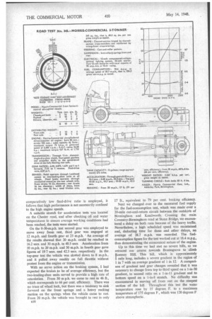
On the 0-30-m.p.h. test second gear was employed to move away from rest, third gear was engaged at 12 m.p.h. and fourth gear at 23 m.p.h. An average of the results showed that 20 m.p.h. could be reached in 16.2 secs. and 30 m.p.h. in 40.3 secs Acceleration from 10 m.p.h. to 20 m.p.h. and 30 m.p.h. in fourth gear gave figures of 19 7 secs. and 42.3 secs. respectively In the top-gear test the vehicle was slowed down to 8 m.p.h., and it pulled away readily on full throttle without protest from the engine or transmission.
With no servo action on the braking system, I had expected the brakes to be of average efficiency, but the two-leading-shoe units served to provide a high rate of retardation. From 30 m p.h. we came to rest in 46 ft., which corresponds to 66 per cent. efficiency. There was no trace of wheel lock, but there was a tendency to sink forward on the front springs and a heavy rocking motion on the springs when the vehicle came to rest. From 20 m.p.h. the vehicle was brought to rest in only n10 17 ft., equivalent to 79 per cent. braking efficiency.
Next we changed over to the measured fuel supply for the fuel-consumption test, which was made over a 20-mile out-and-return circuit between the outskirts of Birmingham• and Kenilworth. Crossing the main Coventry-Birmingham road at Stone Bridge, we encountered a delay on both runs because of the heavy traffic. Nevertheless, a high scheduled speed was maintained and, deducting time for these and other delays, an average of 28.7 m.p.h. was recorded. The fuel-. consumption figure for the test worked out at 18.4 m.p.g., thus demonstrating the economical nature of the engine.
Up to this time we had met no severe hills, so we retraced our course towards Bromsgrove to climb Fbmsey Hill. This hill, which is approximately mile long, includes a severe gradient in the region of 1 in 7 with an average gradient of 1 in 12. A comparison of gradient and gear changes revealed that it was necessary to change front top to third speed on a 1-in-20 gradient, to second ratio on a 1-in-11 gradient and to bottom speed on a 1-in-8 stretch. No difficulty was encountered in moving off from rest on the steepest section of the hill Throughout this test the water temperature rose by 35 degrees F. to a maximum temperature of 175 degrees F., which was 120 degrees F above atmospheric.