


An Improved Junkers Engine
Page 68
If you've noticed an error in this article please click here to report it so we can fix it.
A Resume of Patent Specifications that have Recently been Published
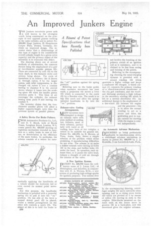
THE Junkers two-stroke power unit is well known in the oil-engine world, being constructed on the principle of two opposed pistons working in the same cylinder, and in patent No. 426,693 Hugo Junkers, 21 Hauptmann Loeper Plats, Dessau, Germany, discloses an improved design. The inventor states that a disadvantage of this type of engine is the considerable overall cylinder length for a given cubic capacity, and the primary object of the invention is to overcome this defect.
The drawing shows one of several methods of construction, the common feature being the employment of a pair of two-diameter annular pistons (5). These are connected by rods (3) to the main shaft, in this instance racks and pinions being shown. The cycle of
• -operations is as follows : Air is drawn in through valves 4 by the larger piston, and, after compression, is discharged via. valves 2 into a conduit leading to chamber 8 in the central sleeve, whence it issues into the working space (6) when the smaller piston uncovers ports 1. This blast of air scavenges the cylinder, the exhaust issuing from ports 9 and .leaving via conduit 7.
The inventor claims that the two diameter annular piston will allow a higher capacity-length ratio than the previous system of parallel pistons.
A Safety Device For Brake Failures.
FFROM Automotive Products Co., Lid., and D. T. Brock, both of Brock House, Langham Street, London, W.1, comes patent No. 426,630 showing an ingenious mechanism intended to function as a safety brake in case of failure, or deterioration in the efficiency of the main brakes. In particular, the scheme consists of a means for auto
matically applying the handbrake of a vehicle should the footbrake fail or even exceed its normal pedal movement.
For this purpose, the handbrake mechanism is provided with a powerful spring (1) to pull it into the "on " position. On one side of the lever a normal detent pawl (2) is placed, whilst a similar ..arrangement on the other side controls a catch (3). The object of this is to bold the brake in
B50 the " oh" position against the spring pressure.
Referring now to the brake pedal, when excessive movement has been made, a projection (4) moves a lever (5) which is connected to the catch (3) by a Bowden wire. The result is to trip this catch and allow the springoperated handbrake to fly into the " on " position.
Exhaust-valve Cooling Arrangements, It /TANI' inventors have al attempted to design an exhaust valve with some method of cooling, but, hitherto, most of these schemes, particularly with water or oil cooling, have been of too complex a nature to be suitable for general use. Patent No. 426,379, by E. Ravera, of Tires, Aosta, Italy, shows a simple solution of the problem which seems promising, if manufacturing difficulties do not arise.. The scheme is to make a hollow exhaust valve having air-holes (2) in the stem, and further holes (1) under the head. In operation, each exhaust blast, as it passes the valve head, induces a draught of cold air through the interior of the valve.
A New Ignition System.
PATENT No. 426,795 hears the wellknown name of J. Lucas, Ltd., of Birmingham, and describes, in conjunction with E. A. Watson, M.Sc., a new system of producing high-voltage sparks for ignition purposes. This scheme does
not involve the breaking of the primary circuit of an ignition coil as is customary, and n is claimed to be free from arcing and burning of the points.
Referring to the accompanying drawing, the usual charging dynamo is provided with a second winding (3) Which generates a higher voltage and keeps a condenser (4) charged. A tithed contact (1) connects the primary winding of a closed-iron-circuit transformer to the cha_ged condenser, and the resultant discharge .produces a high voltage in the secondary winding (6) which is led to a normal distributor (7). An additional feature is the employment of a free-wheel .(2) between the engine and the generator ; this is to allow the normal winding to act as a motor and drive. the generating part to supply current for starting while the engine is rotated independently, An Automatic Advance Mechanism. DESCRIBED as being particularly applicable to injection-pump drive, a centrifugal advance mechanism is shown in patent No. 426,976 by J. J. Bouteille, 3 rue Leconte-de-Lisle, Paris.
In the accompanying drawing, centrifugal weights (5) move outwards when running, and in so doing move levers (2) which are pivoted at 1 by means of rollers (8) moving in slots in the weights. Slide-blocks mounted on the inner, ends of the levers move in grooves ( 4) in a back-plate, and this movement gives the angular advance.