


DESIGN FOR SIX-WHEELED VEHICLES.
Page 32
If you've noticed an error in this article please click here to report it so we can fix it.
A Résumé of Recently Published Patents.
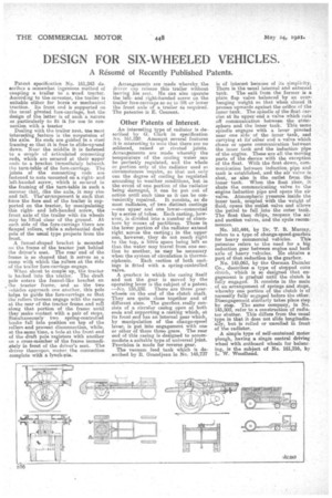
Patent specification No. 161,243 de. acribes a somewhat ingenious method of eoupling a trailer to a troad tractor. According to the anventer, the trailer is suitable either for horde or mechanical traction. Its front end is supported on the usual pivoted fore-carriage, but the design of the latter is of such a nature as .particularly to fit it for use in connection with a tractor
Dealing with the trailer first, the most interesting feature is the suspension of the axle. Its ends are guided in a steel framing so that it is free to slideeupiand down. Near the middle it is fastened to a couple of articulated connecting rode, which are secured at their upper ends to a bracket. immediately beneath the turn-table of the fore-carriage. The joints of the connecting rods are fastened to nuts mounted on a rightand left-handed screw, which is secured in the frainieg of the turn-table in such a manner that, like the axle, it may rise The' and fall. arrangement is such that lance the fore end of the trailer is supported on the tractor, by manipulating this rightand left-handed screw, the front axle of the trailer with its wheels may be lifted clear of the ground. At each side of the fore-carriage there are flanged rollers, while a substantial draft pole of the weal type projects from the front.
A funnel-shaped bracket is mounted on the frame a the tractor just behind the driver's seat. The rear end of the frame is so shaped that it serves as a
• ramp with which the rollers at the side of the trailer fore-carriage engage. When about to couple up, the tractor
is backed into the trailer. The draft pole enters the funnel-like bracket on , the tractor frame, and as the two vehicles approach one another, this polo helps to guide the fore-carriage so that the rollers thereon engage with the ramp at the rear of the tractor frame and roll along that portion of the frame until they make contact with a pair of stops. Simultaneously two spring-controlled hooks fall into position on top of the rollers and prevent disconnection, while, at the same time, a hole.at the front end of the draft pole registers with another on a cross-member of the frame 'immediately in front of the driver's seat. The driver thereupon makes the connection complete with a lynch-phi.
Arrangements are made whereby the driver eat,' release this trailer without leaving hie seat. He can also operate the leftand right-handed screw on the trailer fore-carriage so as to lift or lower the front axle of a trailer ris required. The patentee is E. Courant.
Other Patents of Interest.
An interesting type of radiator is described by G. Clark in specification o, 161,220. Amongst several features it is interesting to note that there are no soldered, raised or riveted joints. Arrangements are made whereby the temperature of the cooling water can be perfectly regulated, and the whole or portion only of the radiator used as circumstances require, so that not only can the degree of cooling be regulated according to weather conditions, but in the event of one portion of the radiator being damaged, it can be put out of action until such time as it can be con veniently repaired. It consists, as do most radiators, of two distinct, castings —one upper and one lower—connected by a series of tubes. Each casting, however, is divided into a number of chambers by nines of partitions. Those in the lower portion of the radiator extend right across the casting; in the upper ono, however, they do not reach right to the top, a little space being left 60 that the water may travel from one see-. Von to another, as may be necessary when the system of circulation is thermo
siphonic. Each section of both castings is fitted with a spring-controlled valve.
A gearbox in which the casing itself and not the gear is moved by the operating lever is the subject of a patent —No. 155,232. There are three gearwheels on the end of the clutch shaft. They are quite close together and of different sizes. The gearbox, really consista of a circular casing open at both ends and supeorting a casting which, at its front end teas an internal gear which, by manipulation of the change-speed lever, is put into engagement with one or other of these three gears. The rear end of this casing is designed to accommodate a suitable type of universal joint. Provision is made for reverse gear.
The vacuum feed tank Which is described by R. Grandjean in No. 145,737
is of interest because of its simplicity. There is the usual internal area external tank. The exit from the former is a plain flap valve balanced by an overhanging weight so that when closed it presses'upward's against the orifice of the inner tank. The spindle of the float carries at its upper end a valve which cuts off communication between the atmosphere and the inner tank. This same spindle engages with a lever pivoted near one side of the inner • tank, and carrying at its other end a valve which closes or opens communication between the inner tank and the induction pipe of the engine. These are all the moving parts of the device with the exception of the float. With the float down, communication between induction, pipe and tank is established, and the air valve is shut, as also is the outlet from the inner tank. When the float rises, it shuts the communicating valve to the engine induction pipe and opens the air valve. Atmospheric pressure inside the inner tank, coupled with the weight of fluid, opens the outlet valve and allows the petrol to fall into the outer tank. The float then &Zips, reopens the air and suction valves, and the cycle recommences.
N. 161,444, by Dr. T. B. Murray, refers to a type of change-speed-gearbox for heavy commercial vehicles. This patentee refers to the need tor a big reduction gear between engine and back axle of heavy vehicles. He obtains a part of that reduction in the gearbox. No. 145,063, by the German Daimler Co.' describes a type of 'stepped cone clutch, which is so designed that engagement is gradual until the clutch is fully engaged. It consists in the main of an arrangement of springs and stops, whereby one portion of the clutch is of necessity fully engaged before the other. Disengagement similarly takes place step by step. The same company, in No. 145,500, refer to a construction of radiator shutter. This differs from the usual type in that it does not slide lougitudina y, but is rolled or unrolled in front of the radiator.
A simple type of self-contained motor plough, having a single central driving wheel with outboard wheels for balancing, i9 the subieet of No. 161,216, by L. W. Woodhead.