


With Intent to Improve.
Page 20
If you've noticed an error in this article please click here to report it so we can fix it.
A Weekly Summary of Recent Patents, of Interest to the Maker and User of Commercial Motor Vehicles.
Selected and Abridged by H. S. Hall, A..M.I.A.E.
An Improved Splash Guard.
A difficulty with regard to the design .of splash guards is that they are very liable to he damaged, detached, or otherwise suffer through contact with obstacles in the roadway, and particularly by being crushed between the vehicle wheels and the kerlastone.
H. V. N. Graveley, of 5, Golders Ease, Hendon, in his patent No. 105398, claims
to have arrived at a solution of this trouble. His guard consists of three main parts, as shown. in the drawing we reproduce. The top part is hung from the wheel hub, and is capable of movement in its own plane. To the lower edge of this, and attached by a pair of hinges, thus rendering it movable in a direction at:right angles to its phinesis the, seCend part. The third portion, which is in two pieces; is hung from the second by two pairs of paralle/ link's; one pair to each half. The Miter link. of each pair. carries at its upper end an outwardly projecting riece; which is in contact -with a similar abutment • attached to the firstnamed part of the guard., . It will he gathered that an object struck endwise by the 'guard may move it bodily round the wheel hub. If the guard meets-an obstacle sideways, the guard, under the action of the abiltments and links, bends inwards, -and at the same time lifts, as shown by the second part of ,surillustratios. There are six claims, the first, and principal one, covers a side splashguard as described, adapted to be raised, and fold or collapse simultaneously, on encountering an obstruction. The others refer to .its construssion—it is in three main pieces—to the sitspnsion of the lowest portion by links, and to the method of causing it to collapse upon
A Steam Engine Governor.
Clayton and Sbutileworth, 'Ad., and F. .1. Bretherton.' both of Stamp End Works, . Lincoln, described a simplified form of governor for ,a steam engine, in specification 105430. It is for use in connection with steam engines of the type which embodies poppet valves for condoning the supply and exhaust isf the steam, these poppet valves being operated by. means of a camshaft. It is customary m such engines, when fitted with governors, for the latter to effect longitudinal movement of the camshaft, so that different shaped portions of the cams" are brought to bear on the tappet-4, effecting a corresponding alteration to the steam distribution. The present patent, as applied to this arrangement, covers the mounting of the governor SO that it directly controls the end-. w.isa movement of the camshaft, being mounted. on it. The immediate result, from a mechanical point of view, is good, it effects a considerable saving in pins and joints besides tending to simplification of the valve operating mechanism. It should also have the effect of making the action of the governors more sepias.: Our illustration is reproduced from one of the drawings filed with the Speeificatign. It will be seen'that the camshaft is driven by a pair of -Amy gears, that on the camshaft being keYed to a sleeve, itself bored so that the camshaft, whilst
• being" i compelled to sevolve with t, may nevertheless move longitudinally inside • it. • The governor arms are attached to one end of this sleeve, their other ends being secured to the camshaft. Expansion of the governor moves the camshaft and brings different portions of the cams into operation. . The cams are so shaped that the admission points of the steam • are the same for all positions of the governor, on y the , cut-off point lacing effected by this movement. A „spring pressing on the end of the camshaft resists the action bf the governor, and is adjustable. The principal of the two claims is for a centrifugal governor mounted directly on the camshaft.
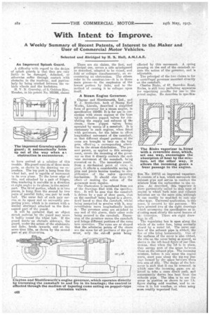
Charles Binks, of 67, Snowdon Read, Eccles, is still busy perfecting apparatus for vaporizing paraffin for use 'in the patrol engine. He describes in speciaea
tion:Ncr. 104715 an improved vaporizer. It consists of a box,, which surrounds the exhaust pipe and serves to "conduct the mixture from the carburetter to the engine. As described, this vaporizer is more particularly suited to that type of engine in which bath inlet and exhaust -branches are on the same side, "although it can readily . be modified to Suit any other type. Universal application, in this sense, is covered by the patentee. We have selected two of the eight drawings which accompany the specification as indicating most clearly the novel feature of tli 'invention. There afe eight drawings in all.
The vaporizing box is open along the whole of its outer face, being normally closed by a metal lid. The outer surface of the exhaust pipe is ribbed, the -fins or ribs lying horizontally. One, of the " surfaces of the cover is also ribbed, the ribS on the cover-"being so spaced, .as shown in the left-hand figure of our illustration, -that when the lid. is in place, they occupy part of the space between those on the exhaust pipe. The incoming mixture, before it can enter the engine ports, must pass along the zig-sag passage formed by the space between these two sets of ribs. The design of the boxcover is such that it can be reversed, in which case the incoming gases are allowed to take a more direct path, and consequently derive less heat from the exhaust pipe. The idea is to rue the cover in position as shown in Cur l.h. figure during cold weather, And to reverse it in hot weather, or, when asing .moito readily vaporized fuel.