


Pilot Injection for Small Engines
Page 70
If you've noticed an error in this article please click here to report it so we can fix it.
THE provision of pilot injection for small engines is complicated by the fact that, as the charge itself is so small, it is difficult to measure off a small part of it, due mainly to the inevitable leakages in the pump. An injection system claimed to be better in this respect comes in patent No.
728,697, from G. Green, Rowans, Monks Road, Virginia Water, Surrey.
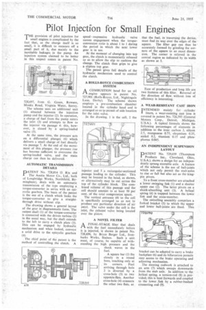
The scheme uses an additional unit (I) situated between the injection pump and the injector (2). In operation, a charge of fuel from the pump enters the inlet (3) and attempts to flow to the injector via passage 4: this, however, is closed by a spring-loaded valve (5).
At the same time, the pressure acts on a differential plungec (6) which delivers a small charge of fuel directly via passage 7. At the end of the movement of this plunger, the pressure rise has become sufficient to overcome the spring-loaded valve, and the main charge can then be delivered.
• AUTOMATIC TRANSMISSION DETAILS
DATENT No. 728,814 (J. Rix and I The Austin Motor Co., Ltd., both of Longbridge Works, Northfield, Birmingham), deals with an automatic transmission of the type employing a torque-converter in series with an epicyclic gearbox. The basis of the patent is the use of a clutch which locks the torque-converter to give a straightthrough drive without slip.
The drawing shows a general layout of the gear in diagrammatic form. The output shaft (1) of the torque-converter is connected with the driven turbine (2) in the usual way, but the shaft extends to the left to carry a clutch plate (3). This can be engaged by hydraulic mechanism and when locked, conveys a solid drive to the epicyclic gearbox (4).
The chief point of the patent is the method of controlling the clutch. A speed responsive hydraulic valve causes engagement when the torqueconversion ratio is about 1 to 1 during the period in which the next lower gear is in use.
At the moment of changing into top gear, the clutch is momentarily released so as to allow the slip to cushion the change. The clutch then grips to give a slipless top gear.
The patent gives full details of the hydraulic mechanism used to control the clutch.
A ROLLS-ROYCE COMBUSTION SYSTEM
PAA COMBUSTION head for an oil engine appears in patent No. 727,901 (Rolls-Royce, Ltd., Nightingale Lane, Derby). The scheme shown employs a pre-combustion chamber located in the cylinder head and is arranged so as to permit of side location for the inlet valve.
In the drawing, 1 is the cell, 2 the
njector and 3 a rectangular-sectioned passage leading to the cylinder. This may be located in the head, as shown, or alternatively may be cut across the top of the cylinder block. The combined volume of this passage and the• cell should amount to at least 50 per cent, of the total compression' space.
The vertical entrance (4) to the cell is specifically arranged so as not to produce any particular direction of air swirl. The valve under the cell is the inlet, the exhaust valve being located over the piston: A NOVEL FILTER
A FINAL-STAGE filter that deals 1-11 with the fuel immediately before it s injected, i shown in patent No. 728,696, by Bryce Berger Ltd., Ironbarks Works, Staines. Such a unit must, of course, be capable of withstanding the high pressure and the shock waves in the fuel.
A square bar (1) fits closely in a round bore, touching only at its corners. Fuel arriving through hole 2 is diverted by a cross-hole (3) to two opposite flats. Another cross-hole (4) connects the other two flats, so that the fuel, in traversing the device, must find its way over the edges of the square. The filter gap can thus be ' accurately formed by grinding the corners of the square to an exact dimension. The corner is relieved in the central region as indicated by its width as shown at 5.
Ease of production and long life are two features of this filter. Reversal of the direction of flow without loss of efficiency is interesting.
A WEAR-RESISTANT CAST IRON
TNTENDED mainly for cylinder I liners, a wear-resisting cast iron is covered in patent No. 726,593 (General Motors Corp., Detroit, Michigan, U.S.A.). A typical formula shows the following percentages of elements in addition to the iron: carbon 3, silicon 2.5, manganese 0.75, chromium 0.35, nickel 0.2, titanium 0.15 and phosphorus 0.045.
AN INDEPENDENT SUSPENSION LAYOUT 111111ATENT No. 729,039 (Thompson I Products Inc., Cleveland, Ohio, U.S.A.), shows a design for an independently sprung stcerable axle. A feature of the scheme is the use of ball-joints which not only permit the stub-axles to rise or fail but also act as the kingpin pivots.
To a front cross-member are attached a lower swinging link (1) and a shorter upper one (2). The latter pivots on a shock-absorbing unit (3). A helical spring (4) is trapped between the lower link and the cross-member.
The swivelling assembly comprises a forked bracket (5) to which the upper and lower ball-joints are fixed. This bracket can be adapted to carry a brake backplate (6) and its bifurcation permits easy access to the brake operating and adjusting mechanism.
The steering rodwork is attached to an arm (7) which sweeps downwards from the stub axle. In addition to the helical spring, a torsion-rod (8) is provided; this is bent forwards and coupled to the lower link by a rubber-bushed connecting rod (9).